
The Hidden Dangers of Improper Receptacle Wiring
Wiring electrical receptacles seems like a straightforward DIY task, but hidden behind the faceplate are critical connections that handle thousands of watts of continuous power. According to the U.S. Consumer Product Safety Commission (CPSC), faulty electrical outlets and wiring are responsible for thousands of home fires annually. Loose terminal screws, improper wire stripping, and outdated 'backstab' push-in connections lead to arcing, thermal expansion, and catastrophic failure.
This comprehensive, step-by-step guide moves beyond basic advice. We will cover exact stripping measurements, National Electrical Code (NEC) torque requirements, and the specific tools professional electricians use to ensure a fire-safe, code-compliant installation in 2026.
Receptacle and Wire Gauge Matrix
Before touching a wire, you must match the receptacle rating to the circuit breaker and wire gauge. Mismatching these is a primary cause of electrical fires. The Occupational Safety and Health Administration (OSHA) strictly enforces these ampacity limits in commercial settings, and they are equally critical in residential wiring.
| Receptacle Type | NEMA Config | Breaker Size | Wire Gauge (Copper) | Common Application |
|---|---|---|---|---|
| Standard 15A | 5-15R | 15 Amp | 14 AWG | Bedrooms, Living Rooms |
| Standard 20A | 5-20R | 20 Amp | 12 AWG | Kitchens, Bathrooms, Garages |
| 15A on 20A Circuit | 5-15R | 20 Amp | 12 AWG | General 20A circuits (NEC 210.21) |
Critical Warning: Never install a 20A receptacle (NEMA 5-20R) on a 15A circuit with 14 AWG wire. Furthermore, never use 14 AWG wire on a 20A breaker. The breaker will not trip before the 14 AWG wire melts and ignites the surrounding framing.
Essential Tools for Code-Compliant Wiring
Skip the cheap multi-tools. Proper wiring requires precision instruments to prevent nicked conductors and loose connections.
- Wire Strippers: Klein Tools 11055 (10-18 AWG). Features precise shear holes to strip insulation without scoring the copper. (~$24)
- Non-Contact Voltage Tester: Ideal 33-099 or Fluke 1AC-II. Dual-range sensitivity ensures you don't get false negatives on low-voltage induction. (~$25)
- Torque Screwdriver: CDI Torque 2101RMAFRSP or similar, adjustable to inch-pounds. Required by NEC 110.14(D). (~$120)
- Connectors: Wago 221-413 Lever Nuts for pigtailing. Superior to traditional twist-on wire nuts for solid-to-stranded connections. (~$0.60 each)
- Receptacles: Leviton T5320-W (15A) or T5262-W (20A). Spec-grade, Tamper-Resistant (TR), with side-clamp plate terminals. (~$4.50 each)
Step-by-Step Installation Process
Step 1: Power Isolation and Verification
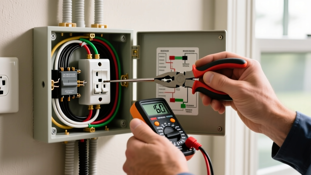
Turn off the circuit breaker at the main panel. Do not rely solely on a wall switch. Insert your non-contact voltage tester into both the top and bottom slots of the existing receptacle. Test the tester on a known live circuit before and after to verify the tool's battery and functionality. Lock out the panel if you are working in a shared space.
Step 2: Cable Preparation and Precision Stripping
When stripping the outer NM-B (Romex) jacket, leave exactly 1/4 inch of jacket inside the electrical box to protect the wire insulation from the rough metal box edges. Strip exactly 3/4 inch of insulation from the individual black (hot) and white (neutral) conductors. If you strip too little, the insulation will bind under the terminal screw, causing a high-resistance connection. If you strip too much, you will expose bare copper outside the receptacle yoke, creating a short-circuit hazard when pushed back into the box.
Step 3: Side-Wiring and Torque Specifications
Never use the 'backstab' push-in holes on the rear of standard builder-grade receptacles. These rely on a tiny internal spring clip that loosens over years of thermal cycling (heating and cooling under load), leading to arcing.
Instead, use the side terminal screws or the side-clamp plates found on spec-grade Leviton or Hubbell receptacles. Form a 'J-hook' in the bare copper using needle-nose pliers. Hook the wire around the terminal screw in a clockwise direction. This ensures that tightening the screw pulls the loop tighter, rather than pushing it out.
The Torque Requirement: Under NEC 110.14(D), connections must be tightened to the manufacturer's specified torque. For most Leviton 15A and 20A spec-grade receptacles, the terminal screws require 12 to 14 inch-pounds of torque. Use a calibrated torque screwdriver for the final turn. This eliminates the guesswork that leads to crushed wires (over-tightening) or loose connections (under-tightening).
Step 4: Pigtailing for Circuit Continuity
If the receptacle is in the middle of a run (meaning wires are entering and exiting the box to feed downstream outlets), do not rely on the receptacle's internal brass and silver straps to carry the load to the next outlet. If the receptacle fails or is removed, the downstream circuit dies. More importantly, NEC 300.13(B) requires the continuity of the grounded (neutral) conductor in multi-wire branch circuits.
The Pro Method: Use Wago 221-413 lever connectors to pigtail the hot, neutral, and ground wires. Connect the incoming and outgoing wires to the lever nut, along with a 6-inch pigtail wire that connects directly to the receptacle. This guarantees uninterrupted circuit continuity and makes future troubleshooting vastly easier.
Step 5: Box Packing and Mounting
Fold the wires into the box in an accordion or 'Z' pattern. Push the ground wires to the very back of the box. Fold the neutral wires next, and finally, tuck the hot wires neatly on the sides. Forcing a tangled bird's nest of wires into a standard 18-cubic-inch box can damage the insulation and create excessive heat buildup. Secure the receptacle to the box using the provided 6-32 machine screws, ensuring the yoke sits flush against the drywall or plaster ring.
2026 Code Updates: GFCI and AFCI Integration
When wiring electrical receptacles in modern renovations, you must adhere to the latest NEC expansions for ground-fault and arc-fault protection. As of the most recent code cycles, GFCI protection is mandated for all 125V through 250V receptacles in areas with sinks (kitchens, bathrooms, laundry, garages, outdoors, and within 6 feet of any wet bar or utility sink). Furthermore, AFCI protection is now required in virtually all living spaces, including kitchens and laundry rooms, which historically only required GFCI. When installing a dual-function (CAFCI/GFCI) breaker, ensure the neutral pigtail from the breaker connects directly to the panel's neutral bar, and the circuit's neutral connects to the breaker's designated terminal.
Frequently Asked Questions (FAQ)
Can I daisy-chain receptacles without pigtailing?
While the NEC allows you to use the receptacle's internal straps to pass power to the next outlet on a standard 2-wire branch circuit, it is considered poor practice. Pigtailing ensures that a loose terminal screw on one outlet won't kill power to the rest of the room. Always pigtail the neutral wire in a Multi-Wire Branch Circuit (MWBC).
Why do my wires keep slipping out of the backstab holes?
Backstab holes are designed strictly for 14 AWG solid copper wire. If you attempt to insert 12 AWG wire, or if the wire is stranded, it will not seat correctly in the internal grab-ring. Abandon backstabbing entirely and use side-wiring with proper torque.
How do I wire a receptacle with a red, black, white, and ground wire?
This indicates a Multi-Wire Branch Circuit (MWBC) or a switched half-receptacle. If the red and black wires are on different phases sharing a single white neutral, you must use a 2-pole breaker and pigtail the neutral. If the red wire is feeding a wall switch to control the top half of the outlet, you must break the brass 'hot' side tab on the receptacle while leaving the silver 'neutral' tab intact.
Final Verification
Once the faceplate is installed and power is restored, do not assume the wiring is correct just because the outlet works. Use a receptacle tester like the Gardner Bender GRT-350. Plug it in and verify the light sequence indicates 'Correct Wiring'. Test the GFCI button if applicable. Properly wiring electrical receptacles is about precision, code adherence, and respecting the physics of electrical resistance. Take your time, torque your connections, and prioritize safety over speed.