
Initial Safety Protocol & Diagnostic Tool Requirements
When a receptacle suddenly loses power, the root cause ranges from a simple tripped breaker to a hazardous melted neutral wire inside the wall cavity. According to the National Fire Protection Association (NFPA), electrical distribution and lighting equipment are consistently among the top causes of home structure fires. Before attempting any physical repair, you must methodically isolate the failure point.
To perform a professional-grade diagnosis and re-installation, gather the following tools:
- Non-Contact Voltage Tester (NCVT): Klein Tools NCVT-3 (approx. $28) for initial dead-front verification.
- Digital Multimeter (DMM): Fluke 117 True-RMS (approx. $210) or a budget alternative like the AstroAI DM6000AR (approx. $35) for precise voltage drop and continuity testing.
- Receptacle Tester: Gardner Bender GFI-3501 (approx. $12) for post-repair ground fault verification.
- Torque Screwdriver: Wiha 645P or Klein 650 (approx. $65-$90) to meet modern NEC termination standards.
- Wire Strippers & Lineman Pliers: Klein 11055 and 2000 series.
Phase 1: Upstream Diagnostics (No Disassembly Required)
Before unscrewing a single faceplate, rule out upstream interruptions. Roughly 60% of dead outlet complaints are resolved in this phase without ever touching a screwdriver.
Step 1: The GFCI and AFCI Cascade Check
Modern electrical codes require Ground Fault Circuit Interrupter (GFCI) protection in wet areas and Arc Fault Circuit Interrupter (AFCI) protection in living spaces. A standard bedroom outlet may be wired to the 'LOAD' terminals of a GFCI receptacle located in an adjacent bathroom, garage, or exterior wall.
- Identify all GFCI receptacles in your home (look for the 'Test' and 'Reset' buttons).
- Press the 'Reset' button firmly on each unit. If a button clicks and stays depressed, you have found the upstream trip.
- Check your main electrical panel for AFCI breakers. These feature a digital display or an LED indicator and a distinct 'Test' button. If the breaker flag is in the middle (tripped) position, turn it fully OFF, then snap it ON.
Step 2: Breaker Panel Verification & Voltage Mapping
If no GFCI/AFCI devices have tripped, move to the main service panel. A breaker may appear 'ON' but be internally tripped. Toggle the suspect breaker fully to the OFF position, then back to ON. If the dead outlet remains unpowered, proceed to physical teardown.
Phase 2: Teardown and Internal Inspection
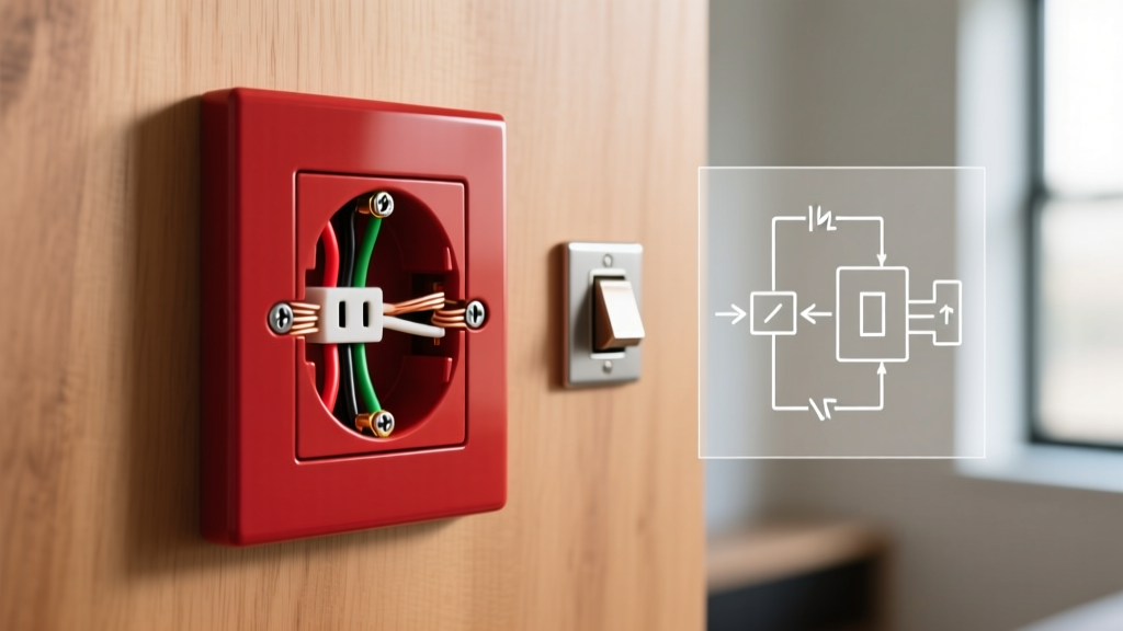
With the circuit breaker turned OFF and locked out (or taped), use your NCVT to verify the absence of voltage at the receptacle slots. Remove the center screw and pull the receptacle yoke out of the junction box. Do not touch bare wires until you have tested them with a multimeter.
Step 3: Multimeter Voltage & Continuity Testing
Set your multimeter to AC Voltage (V~). With the breaker temporarily turned back ON (exercise extreme caution), probe the terminals:
- Line to Neutral (Brass to Silver screw): Should read 120V (±5V).
- Line to Ground (Brass to Green screw): Should read 120V.
- Neutral to Ground (Silver to Green screw): Should read 0V to 2V. A reading higher than 3V indicates a loose neutral connection upstream, which is a severe fire hazard.
After testing, turn the breaker OFF again. Inspect the physical wiring for the failure modes detailed in the matrix below.
Diagnostic Matrix: Common Outlet Failure Modes
| Failure Mode | Root Cause & Metallurgy | Visual Symptom | Repair Action |
|---|---|---|---|
| Push-In (Backstab) Failure | Internal brass spring loses tension over 5-10 years due to thermal expansion/contraction cycles, causing high resistance and arcing. | Brown/black scorch marks on the back plastic housing; melted wire insulation. | Cut back damaged wire, strip 3/4 inch, and terminate on side screw terminals. |
| Loose Neutral Pigtail | Wire nut connection in the back of the box vibrated loose or was improperly twisted, breaking the return path. | Receptacle reads 120V on NCVT but drops to 0V under load (e.g., when plugging in a lamp). | Redo wire nut splice using a Wago 221 lever connector (approx. $0.50 each) for a gas-tight, vibration-proof bond. |
| Broken Yoke / Tab | The brass connecting tab between the top and bottom hot terminals was accidentally snapped off during a previous split-receptacle installation. | Top half of the outlet works (switched), but the bottom half is permanently dead. | Replace the receptacle; ensure the new hot tab is intact unless a split-wired setup is intentionally required. |
| Multi-Wire Branch Circuit (MWBC) Open Neutral | Shared neutral wire disconnected while two hot legs (Leg A and Leg B) are still energized. | Devices plugged into the circuit experience 240V instead of 120V, instantly destroying electronics. | Stop immediately. Install a handle tie on the two adjacent breakers and repair the neutral splice. Consult a licensed electrician if unsure. |
Phase 3: Step-by-Step Re-Installation (NEC Compliant)
Once the failure point is identified, you must re-install or replace the receptacle according to current National Electrical Code (NEC) standards. The Consumer Product Safety Commission (CPSC) emphasizes that improper termination is a leading cause of residential electrical fires.
Step 4: Wire Preparation & Termination
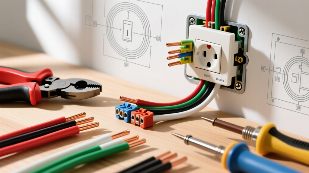
If the existing wires are scorched or brittle, cut them back to fresh copper. Use your wire strippers to remove exactly 3/4 inch of insulation. This ensures the wire wraps completely around the terminal screw without exposing bare copper outside the screw head, which could cause a short circuit against the metal junction box.
- Form a 'shepherd's hook' in the copper wire using the nose of your lineman's pliers.
- Hook the wire around the terminal screw in a clockwise direction. This ensures that tightening the screw pulls the loop closed rather than pushing it out.
- Use only the side screw terminals. Never use the backstab push-in holes, even if the manufacturer includes them.
CRITICAL CODE UPDATE: NEC 110.14(D) Torque Requirements
As of recent NEC cycles (and strictly enforced in 2026 inspections), all terminations must be tightened to the manufacturer's specified torque using a calibrated torque screwdriver. For a standard Leviton T5320-W 15A Tamper-Resistant receptacle, the required torque is typically 14 in-lbs. Guessing the tightness by hand leads to under-torqued connections that arc, or over-torqued screws that strip the brass threads.
Step 5: Box Dressing & Final Testing
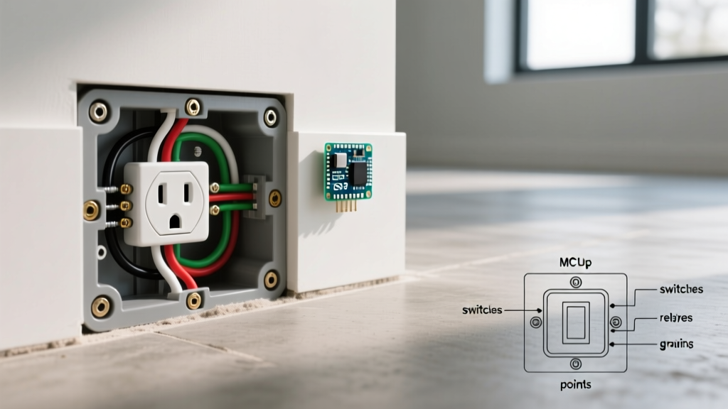
Carefully fold the wires into the back of the junction box. Push the ground wires in first, followed by the neutrals, and finally the hot wires. This 'Z-fold' method prevents pinching wires against the metal box edges, which can cause ground faults.
- Mount the receptacle yoke using the provided 6-32 mounting screws.
- Install a new, unbroken nylon faceplate (avoid vintage or cracked plates that compromise the flush mount).
- Restore power at the breaker panel.
- Insert your Gardner Bender receptacle tester. You should see two amber lights indicating 'Correct Wiring'. If you see a red light or a single amber light, you have a bootleg ground or open neutral that requires immediate re-inspection.
Edge Case: When the Outlet is Fine, but the Device is Not
Occasionally, the receptacle is outputting a perfect 120V, but high-draw appliances (like space heaters or window AC units) fail to operate. This is often caused by voltage drop across a long wire run. If your outlet is at the end of a 100-foot run of 14 AWG wire, pulling 15 amps will result in a voltage drop of nearly 10 volts, leaving only 110V at the terminal. While this won't stop a phone charger from working, it will cause motor-driven appliances to stall and overheat. The U.S. Department of Energy recommends upgrading long runs to 12 AWG or 10 AWG copper to mitigate voltage drop in modern, high-load households.
When to Call a Licensed Electrician
While replacing a standard duplex receptacle is a straightforward DIY task, you must halt your step-by-step installation and call a licensed professional if you encounter:
- Aluminum Wiring: If the wire is silver-colored (common in homes built between 1965 and 1973), standard copper-rated receptacles will cause galvanic corrosion and fire. You need CO/ALR rated receptacles or Alumiconn pigtailing.
- Knob and Tube / Cloth Braided Insulation: Pre-1950s wiring lacks a ground path and the insulation crumbles upon manipulation. Do not disturb it without an electrician's assessment.
- Buzzing or Burning Smells from the Panel: If the breaker itself feels hot to the touch or emits a buzzing sound when the circuit is loaded, the breaker bus stab may be damaged, requiring a panel repair or replacement.
By methodically following this diagnostic and installation protocol, you ensure your home's electrical system remains safe, code-compliant, and fully operational for decades to come.