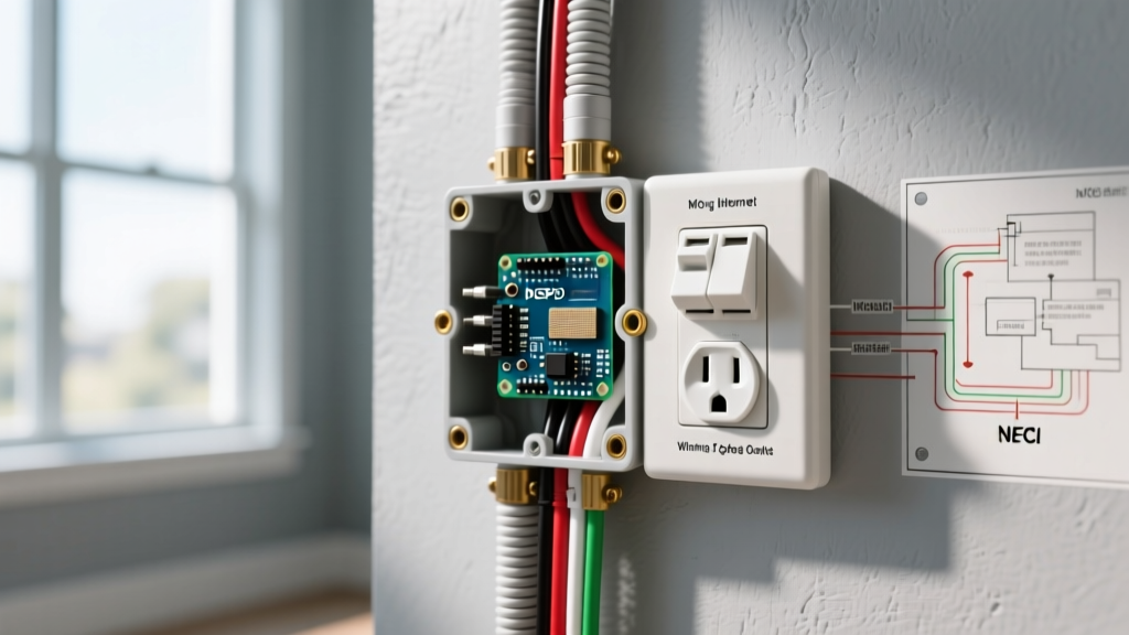

Opening a junction box only to find a weird electrical outlet is a rite of passage for DIYers, home inspectors, and apprentice electricians alike. Whether you are staring down a T-slot 20-amp receptacle, an orange-faced isolated ground plug, or a split-wired duplex with a confusing array of red and black wires, these unconventional devices serve highly specific purposes dictated by the National Electrical Code (NEC).
In this comprehensive wiring diagram reference, we decode the most common unusual receptacles found in residential and commercial settings. We provide exact wiring parameters, torque specifications, failure modes, and NEC compliance rules to ensure your installation is both functional and legally compliant.
The NEMA 5-20R 'T-Slot' Receptacle (20-Amp)
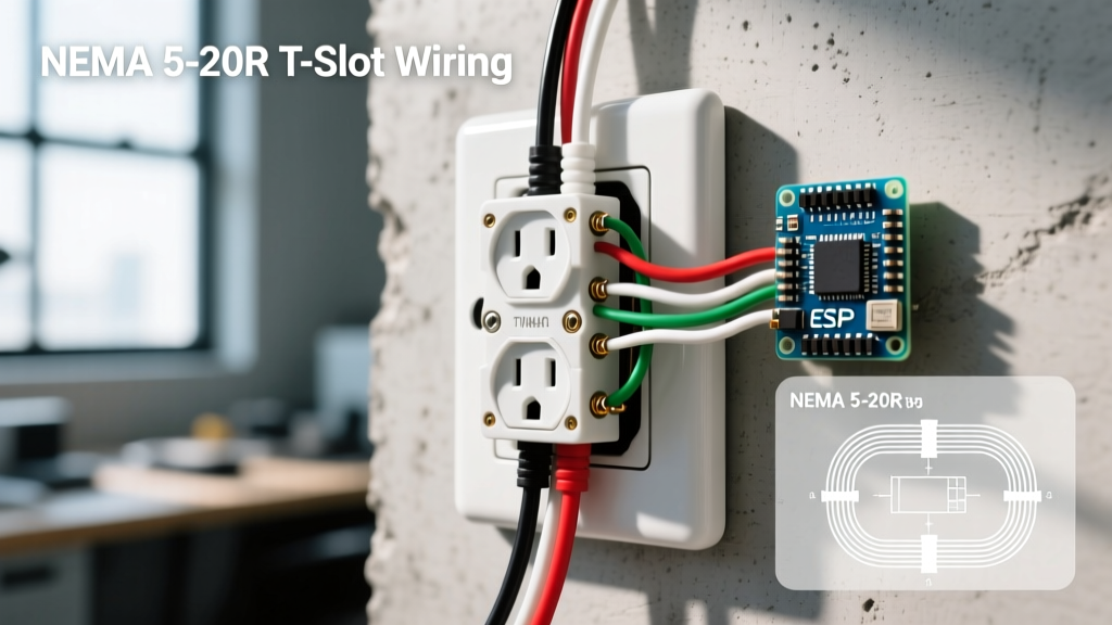
The most frequently encountered 'weird' outlet in modern homes is the NEMA 5-20R. It looks like a standard 15-amp duplex receptacle, but one of the vertical slots is rotated 90 degrees to form a 'T' shape. This design prevents standard 15-amp plugs from being inserted into a 20-amp circuit, though it allows 20-amp appliances (with one horizontal prong) to draw heavy loads safely without overheating the conductors.
Wiring Parameters & NEC Requirements
- Wire Gauge: 12 AWG copper minimum (NEC 240.4(D)). Never use 14 AWG on a 20A breaker, as the wire will melt before the breaker trips.
- Breaker Size: 20-Amp single-pole.
- Wire Stripping: Strip exactly 5/8 inch of insulation. Exposed copper outside the terminal yoke creates a shock hazard and a potential short-circuit point.
- Torque Specification: Under NEC 110.14(D), terminals must be tightened to the manufacturer's specifications. For a standard Leviton 5262-W 20A receptacle, this is typically 14 in-lbs. Use an insulated torque screwdriver to prevent loose connections that cause arc faults over time.
NEC 210.23(A) Note: You can install a 20-amp T-slot receptacle on a 20-amp circuit even if you only plug in 15-amp devices. However, you cannot install a 20-amp receptacle on a 15-amp circuit. The receptacle rating must not exceed the branch circuit rating.
The Orange Face 'Isolated Ground' (IG) Receptacle
If you encounter an outlet with a bright orange face and a small green triangle, you are looking at an Isolated Ground (IG) receptacle (e.g., Hubbell 5262-I). These are common in hospitals, recording studios, server rooms, and high-end home theaters. The 'weird' wiring behind it involves an extra ground wire that bypasses the metal junction box and conduit, running all the way back to the main service panel or a dedicated grounding busbar.
Why Use an Isolated Ground?
Standard grounding paths through metal conduit or standard ground wires can pick up electromagnetic interference (EMI) and 'dirty power' noise from other devices on the same grounding network. An IG receptacle provides a clean, dedicated path to earth ground, protecting sensitive microprocessors, medical equipment, and audio gear from data corruption or 60Hz hum.
Wiring Diagram Logic (4-Wire Setup)
- Hot (Black): Connect to the brass terminal.
- Neutral (White): Connect to the silver terminal.
- Equipment Ground (Green/Bare): Connect to the metal junction box and the standard green grounding screw on the receptacle yoke.
- Isolated Ground (Green with Yellow Stripe): Connect only to the isolated ground terminal (usually marked with an orange dot or separate green screw insulated from the metal yoke). This wire must run unspliced back to the panel.
The Split-Wired (Half-Switched) Duplex Receptacle
Often found in living rooms and bedrooms built before the widespread adoption of smart lighting, a split-wired receptacle features a top half that is always hot and a bottom half controlled by a wall switch. The 'weird' factor here is the wiring inside the box: you will find a 3-wire cable (14/3 or 12/3 NM-B) containing black, red, white, and bare copper wires, and the brass fin (tab) on the hot side of the receptacle will be snapped off.
Step-by-Step Split Receptacle Wiring
- Break the Tab: Using needle-nose pliers, snap off the small brass connecting tab between the two brass (hot) screws. Leave the silver (neutral) tab completely intact.
- Always-Hot (Black Wire): Connect to the top brass screw.
- Switched-Hot (Red Wire): Connect to the bottom brass screw.
- Neutral (White Wire): Connect to either silver screw (they are bridged internally).
- Ground (Bare Copper): Connect to the green grounding screw and pigtail to the metal box if applicable.
Quick Reference Matrix: Unusual Receptacle Configurations
| Receptacle Type | NEMA Code | Visual Identifier | Required Wire Gauge | Breaker Size |
|---|---|---|---|---|
| 20A Standard | 5-20R | One 'T' shaped slot | 12 AWG Copper | 20 Amp |
| Isolated Ground | 5-15R IG | Orange face, green triangle | 14 or 12 AWG | 15 or 20 Amp |
| 30A Dryer (Modern) | 14-30R | 4-prong, L-shaped neutral | 10 AWG Copper | 30 Amp (2-Pole) |
| 50A Range/Welder | 14-50R | 4-prong, large angled pins | 6 AWG Copper | 50 Amp (2-Pole) |
| Twist-Lock (Generator) | L14-30R | Curved prongs, circular face | 10 AWG Copper | 30 Amp (2-Pole) |
The GFCI/AFCI Combination: Line vs. Load Confusion
Another source of confusion is the dual-function GFCI/AFCI receptacle. These devices are deeper than standard outlets (often requiring 2.25-inch deep junction boxes) and feature four terminal screws plus a ground. The most common wiring error is reversing the LINE and LOAD connections.
- LINE Terminals: Connect to the incoming power from the breaker panel. If wired incorrectly here, the outlet will not power on.
- LOAD Terminals: Connect to downstream outlets to extend ground-fault and arc-fault protection. If you wire incoming power to the LOAD terminals, the receptacle may appear to work, but the internal protection circuitry will be bypassed, leaving you vulnerable to lethal shocks.
- Trip Threshold: Per UL 943 standards, the internal solenoid will trip the circuit when it detects a ground-fault current differential of 5 milliamps (±1mA).
Tamper-Resistant (TR) Mechanisms: Why Plugs Won't Insert
Homeowners frequently report that new outlets feel 'weird' or broken because standard plugs refuse to insert. This is the Tamper-Resistant (TR) shutter system, mandated by NEC 406.12 for all 15A and 20A residential receptacles. The internal shutters require simultaneous, equal pressure on both prongs (approximately 1.5 lbs of force per shutter) to open. If a plug is inserted at a slight angle, or if the prongs are bent or of unequal length, the shutters will lock. Always ensure plugs are inserted perfectly straight.
Troubleshooting Edge Cases & Failure Modes
When dealing with unconventional outlets, standard troubleshooting rules still apply, but the failure modes can be significantly more complex.
1. The 'Bootleg' Isolated Ground
A common code violation in older commercial retrofits is jumpering the isolated ground terminal directly to the standard ground terminal or the metal box. This completely defeats the purpose of the IG receptacle and creates a false sense of security for sensitive equipment. To verify, use a digital multimeter (DMM) to measure impedance between the IG pin and the standard ground pin; it should not read zero ohms if the circuit is wired correctly back to the panel.
2. Multi-Wire Branch Circuits (MWBC) on Split Receptacles
If your split-wired outlet is fed by a Multi-Wire Branch Circuit (where the black and red wires are on opposite phases sharing a single neutral), NEC 210.4(B) requires a simultaneous disconnect. This means the two breakers feeding the circuit must be tied together with a handle tie or be a single 2-pole breaker. Failing to do this poses a lethal shock hazard if an electrician turns off only one breaker to work on the receptacle, leaving the shared neutral wire energized by the opposing phase.
For comprehensive safety guidelines and code updates regarding receptacle wiring and grounding, always consult the National Fire Protection Association (NFPA) and review residential electrical safety checklists provided by the Electrical Safety Foundation International (ESFI). Additionally, workplace and commercial grounding standards are strictly regulated; refer to OSHA's electrical safety protocols before modifying isolated ground systems in commercial environments.