
Why Guess When You Can Map the Fault?
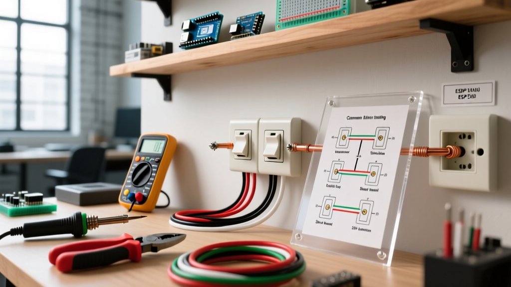
When a standard NEMA 5-15R receptacle fails to deliver power, trips a breaker, or exhibits erratic behavior, amateur electricians often resort to trial and error. Professional troubleshooters, however, rely on an electrical outlet connection diagram to systematically isolate the failure. A wiring diagram is not just an installation guide; it is a diagnostic map. By comparing the physical terminations inside the wall box against the schematic logic of a proper circuit, you can instantly identify dangerous miswires, degraded connections, and code violations that standard plug-in testers frequently miss.
In 2026, with the widespread adoption of smart home diagnostics and stricter AFCI/GFCI mandates, understanding the underlying topology of a 120V branch circuit is critical. This guide details how to leverage connection diagrams to troubleshoot complex receptacle faults, complete with multimeter verification protocols and National Electrical Code (NEC) compliance standards.
The Anatomy of a Standard 120V Receptacle Diagram
Before diagnosing a fault, you must internalize the standard electrical outlet connection diagram for a 120-volt, 15-amp or 20-amp receptacle. The physical device features three distinct terminal zones:
- Brass Terminals (Hot): Connects to the black (or red) ungrounded conductor. This carries the 120V potential from the breaker panel.
- Silver Terminals (Neutral): Connects to the white grounded conductor. This provides the return path to the panel's neutral bus bar.
- Green Terminal (Ground): Connects to the bare copper or green equipment grounding conductor (EGC). This provides a low-impedance fault path to trip the breaker during a short circuit.
A critical feature often omitted in basic tutorials is the break-off fin located between the two brass screws (and occasionally the silver screws). In a standard diagram, this fin remains intact, allowing either backstab or side-wire terminations to feed both the top and bottom receptacles. In split-wired diagrams (common in kitchens and living rooms), this fin must be removed to isolate the top and bottom halves.
Top 5 Wiring Faults and Diagram Corrections
Plug-in receptacle testers (like the standard 3-light neon testers) are notorious for providing false positives. Below is a diagnostic matrix comparing tester readings with true multimeter diagnostics and the corresponding electrical outlet connection diagram corrections.
| Fault Condition | 3-Light Tester Reading | True-RMS Multimeter Verification | Diagram Correction Protocol |
|---|---|---|---|
| Open Neutral | Open (Center light off) | 120V Hot-to-Ground; 0V Hot-to-Neutral | Re-terminate white wire on silver screw; check upstream wire nuts. |
| Reversed Polarity | Rev Pol (Red/Right lights on) | 120V Neutral-to-Ground; 0V Hot-to-Ground | Swap black and white wires to match brass and silver terminals. |
| Hot-Ground Reverse | Danger (Left/Right lights on) | 120V Neutral-to-Ground; 0V Hot-to-Neutral | Immediate shutdown. Black wire is on green screw; bare wire is on brass. |
| Open Ground | Open Ground (Left light only) | 120V Hot-to-Neutral; 0V Hot-to-Ground | Verify EGC continuity to panel; re-terminate bare wire on green screw. |
| Bootleg Ground | Correct (All 3 lights normal) | 0 ohms between Neutral slot and Ground U-slot | Remove neutral-to-ground jumper; run dedicated EGC or install GFCI. |
Deep Dive: Exposing the 'Bootleg Ground' Edge Case
The most dangerous miswire you will encounter is the 'bootleg ground.' This occurs when a previous installer connects a jumper wire between the silver (neutral) terminal and the green (ground) terminal. The intent is to trick a standard 3-light tester into reading 'Correct' so the home passes a superficial inspection.
Because the ground is tied to the neutral at the receptacle, the tester's neon lamp completes its circuit, illuminating the 'Grounded' indicator. However, this violates the fundamental safety premise of the equipment grounding conductor. If a fault occurs downstream, or if the neutral wire becomes loose at the panel, the chassis of any plugged-in appliance (like a microwave or desktop PC) becomes energized at 120V, posing a lethal shock hazard.
How to Diagnose a Bootleg Ground
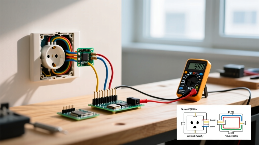
- Resistance Test (Power Off): Turn off the breaker and verify zero voltage. Set your Fluke 117 True-RMS multimeter to Ohms (Ω). Insert the probes into the neutral slot (longer slot) and the ground U-slot. A properly wired circuit will read 'OL' (Open Loop / Infinite resistance). If you read less than 5 ohms, you have a bootleg ground or a neutral-ground bond downstream of the main panel.
- Voltage Drop Test (Power On): Plug a 15A load (like a hairdryer) into the bottom receptacle. Measure the AC voltage between the top receptacle's neutral slot and ground slot. A true, dedicated ground wire will show a potential difference of less than 2V. A bootleg ground will show a significant voltage drop (often 5V to 12V) because the neutral wire's resistance is now carrying the return current for both the appliance and the false ground path.
According to the U.S. Consumer Product Safety Commission, improper grounding and faulty wiring are leading contributors to residential electrical fires and severe shock incidents. Never rely solely on visual inspection or basic plug-in testers to verify ground integrity.
The Split-Receptacle Short Circuit Scenario
When troubleshooting a receptacle that instantly trips the breaker upon resetting, consult the electrical outlet connection diagram for a split-wired (half-hot) setup. In living rooms, it is common for the top half of an outlet to be controlled by a wall switch, while the bottom half remains always-on. This requires a 12/3 or 14/3 Romex cable, utilizing the red wire for the switched leg and the black wire for the constant hot.
The Failure Mode: If a DIYer replaces a split receptacle but forgets to snap off the brass break-off fin, the constant hot (black) and the switched hot (red) are physically bridged inside the device. When the wall switch is turned on, it creates a direct phase-to-phase short circuit (if on a multi-wire branch circuit) or a direct hot-to-hot dead short, violently tripping the breaker. Always verify the brass fin status against your diagram before pushing the receptacle back into the box.
Professional Diagnostic Workflow & Tooling
To execute these troubleshooting steps safely and accurately, specific tools are required. As of 2026, professional electricians rely on the following setup:
- Solenoid Voltage Tester or True-RMS Multimeter: The Fluke 117 ($220-$250) is the industry standard. Its non-contact voltage (NCV) and low-impedance (LoZ) modes prevent false readings caused by ghost voltages in parallel cables.
- GFCI/Receptacle Analyzer: The Klein Tools RT250 ($35-$45) features a solenoid load that can trip GFCI circuits and detect wiring faults without relying solely on neon lamps.
- Torque Screwdriver: The Klein 70906 or Ideal 36-100. NEC Article 110.14(D) strictly requires terminations to be tightened to the manufacturer's specified torque.
Torque Specifications and Code Compliance
A loose neutral connection is a primary cause of arc faults and melted receptacle faces. The National Fire Protection Association (NFPA) enforces strict torque requirements in the NEC. For a standard 15A Leviton 5262-W or Eaton TR15W receptacle, the terminal screws must be tightened to exactly 14 in-lbs (inch-pounds). Backstab (push-in) connections are highly discouraged for troubleshooting and repair, as the internal spring-loaded contacts degrade over time, leading to high-resistance open neutrals. Always use the side-wire terminal hooks or the screw-clamp plates illustrated in high-grade commercial connection diagrams.
Summary: Trust the Schematic, Verify with Data
An electrical outlet connection diagram is your baseline for truth. When physical wiring deviates from the schematic logic, faults occur. By combining diagrammatic analysis with rigorous multimeter testing—specifically targeting hidden dangers like bootleg grounds and split-receptacle shorts—you elevate your troubleshooting from guesswork to professional-grade diagnostics. Always ensure your repairs align with current NEC standards, prioritizing dedicated equipment grounding paths and precise torque specifications to ensure long-term safety and reliability.
For commercial and industrial environments, always cross-reference your residential diagrams with OSHA's wiring design and protection standards, which mandate stricter grounding and GFCI protocols for workplace receptacles.