
What Would Cause an Electrical Outlet to Stop Working? A Wiring Diagram Perspective
When a receptacle suddenly loses power, the immediate assumption is often a tripped breaker. However, from a wiring diagram and circuit topology perspective, the root cause usually lies in physical termination failures, upstream daisy-chain interruptions, or neutral faults. Understanding what would cause an electrical outlet to stop working requires reading the circuit not just as a single point, but as a node in a broader branch circuit.
In this 2026 diagnostic guide, we bypass superficial troubleshooting and analyze the exact wiring schematics, termination mechanics, and Multi-Wire Branch Circuit (MWBC) anomalies that cause receptacles to fail. We will also provide a precise multimeter testing protocol to isolate the fault.
The Anatomy of a Dead Receptacle: Termination Failures
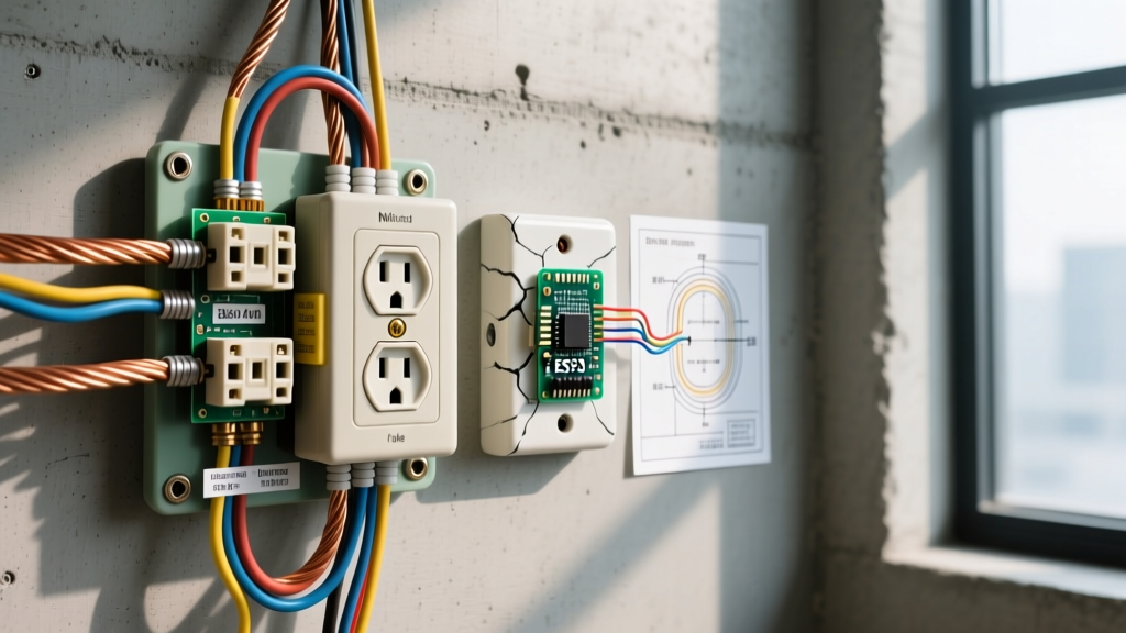
The most common point of failure in residential wiring diagrams is the physical connection at the receptacle terminals. Modern receptacles offer two termination methods: side-screw terminals and push-in (backstab) connectors.
1. Backstabbed Push-In Connections (The Thermal Expansion Fault)
Push-in terminals rely on a small beryllium-copper spring clip to grip 14 AWG solid copper wire. While UL-listed, these connections are highly susceptible to thermal cycling. When a high-draw appliance (like a 1500W space heater pulling 12.5A) is used, the terminal heats up. Over months of expansion and contraction, the spring clip anneals and loses its tensile grip.
- The Diagram Fault: The wiring diagram shows continuity, but the physical connection develops high micro-ohm resistance.
- The Result: Voltage drops across the connection. Eventually, the wire arcs, oxidizes, and creates a complete open circuit, killing the outlet and any downstream nodes.
- The Fix: Never use backstab terminals for 15A/20A circuits. Strip 3/4 inch of insulation and use the side-screw terminals, or upgrade to commercial-grade receptacles like the Leviton T5252 (approx. $4.50), which features patented screw-clamp back-wiring plates that physically trap the wire under a metal plate.
2. Broken Daisy-Chain (Line vs. Load Interruption)
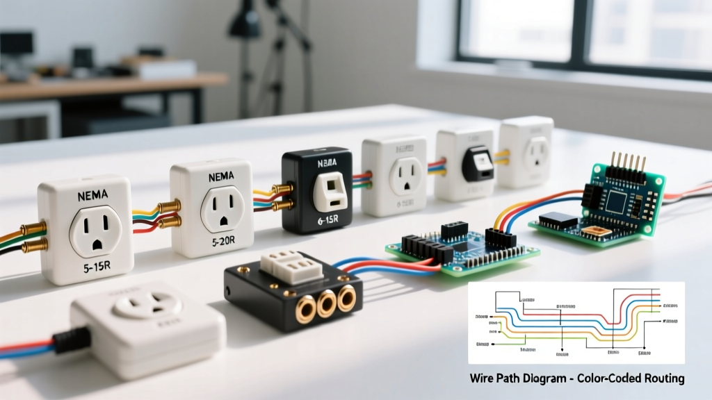
In standard residential wiring, outlets are wired in parallel via a daisy-chain topology. Power enters the 'LINE' terminals and exits via the 'LOAD' terminals to feed the next receptacle. If a wire nut fails in an upstream junction box, or if a LOAD terminal screw backs out due to vibration, the entire downstream chain dies.
Expert Insight: If you test a dead outlet and find 120V on the incoming black (hot) wire but 0V on the outgoing black wire, your wiring diagram fault is an open LOAD connection. Always check the nearest upstream working outlet first.
Complex Circuit Topologies: GFCI and MWBC Faults
Standard termination failures are simple. Complex circuit topologies introduce hidden failure modes that confuse even experienced DIYers.
3. Upstream GFCI/AFCI Tripping and Line/Load Reversal
Under the latest NEC code cycles, kitchens, bathrooms, and garages require Ground Fault Circuit Interrupter (GFCI) protection. A single GFCI receptacle (e.g., Eaton GFTR2-W) often protects multiple standard downstream outlets via its LOAD terminals.
- The Hidden Fault: If an upstream GFCI trips, downstream outlets die. Homeowners often don't realize the dead bedroom outlet is wired to the LOAD terminals of a bathroom GFCI.
- Wiring Diagram Error: If the installer reversed LINE and LOAD on the upstream GFCI, the GFCI will still power its own face, but it will not pass power to the LOAD terminals, leaving downstream outlets dead from day one.
4. Open Neutral in a Multi-Wire Branch Circuit (MWBC)
Kitchen split-receptacles (where the top and bottom outlets are on different breakers) utilize an MWBC. This wiring diagram uses a single 12/3 or 14/3 NM-B cable containing two hot wires (black and red) sharing a single white neutral.
If the shared neutral wire disconnects at the panel or an upstream junction while both hots are energized, the 120V outlets are effectively forced into a series circuit across 240V. This won't just stop the outlet from working; it will send 200V+ to your 120V appliances, instantly destroying them. According to the National Fire Protection Association (NFPA 70), MWBCs now require simultaneous disconnect (handle ties) to prevent this exact electrocution and fire hazard during maintenance.
Diagnostic Matrix: Symptom vs. Wiring Fault
Use this reference table to correlate your physical symptoms with the underlying wiring diagram fault.
| Physical Symptom | Multimeter Reading (Hot-Neutral) | Probable Wiring Diagram Fault | Required Action |
|---|---|---|---|
| Outlet dead, upstream outlet works | 0V | Open LINE connection or tripped upstream GFCI | Check upstream GFCI; inspect LINE pigtails |
| Outlet dead, downstream outlets also dead | 0V | Open LOAD connection at this node | Re-terminate LOAD wires to side screws |
| Dim flickering when appliance turns on | 90V - 110V (under load) | High-resistance backstab connection | Replace receptacle; use screw-clamp terminals |
| Appliances fry / outlet reads ~200V+ | 200V - 240V | Open Shared Neutral on MWBC | Shut off both breakers immediately; repair neutral |
Step-by-Step Multimeter Testing Protocol
To definitively answer what would cause an electrical outlet to stop working in your specific scenario, you must move beyond basic plug-in testers (like the Klein Tools RT210) and use a True-RMS digital multimeter, such as the Fluke 117.
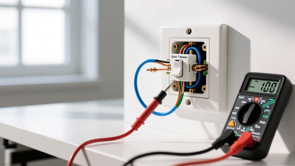
- Verify Tester Safety: Set your multimeter to V AC (Volts Alternating Current). Ensure your test leads are in the COM and V/Ohm ports.
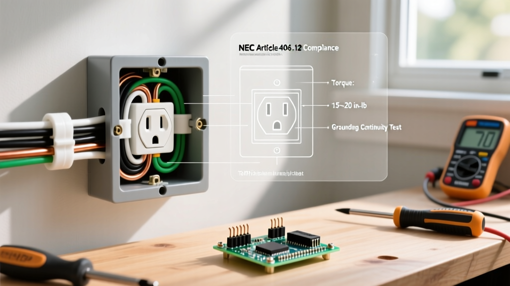
- Test Hot-to-Neutral (H-N): Insert the red probe into the shorter (hot) slot and the black probe into the longer (neutral) slot. A healthy circuit reads 120V (±5%). If 0V, the circuit is open.
- Test Hot-to-Ground (H-G): Move the black probe to the U-shaped ground hole. If H-N reads 0V but H-G reads 120V, you have an Open Neutral. The hot wire is reaching the outlet, but the neutral return path is broken upstream.
- Test Neutral-to-Ground (N-G): Place probes in the neutral and ground slots. This should read less than 1V. If it reads 120V, you have a reversed polarity or a floating neutral hazard.
2026 Repair Costs and NEC Compliance
If you are hiring a licensed electrician to diagnose and repair a dead outlet circuit in 2026, expect to pay between $125 and $185 per hour for diagnostic and repair labor, plus a standard service call fee of $75-$125. A simple backstab replacement usually takes under 30 minutes, but tracing an open neutral inside a finished wall can push the bill past $400.
For DIY repairs, the material cost is minimal. A premium tamper-resistant (TR) receptacle costs about $3.50 to $6.00. However, the Electrical Safety Foundation International (ESFI) strongly emphasizes that any replacement receptacle in a modern home must be Tamper-Resistant (TR) to meet current safety codes, preventing children from inserting foreign objects into the slots.
Final Wiring Diagram Takeaway
When an outlet stops working, do not just swap the plastic faceplate. Trace the wiring diagram logic: verify the upstream node, check for LOAD-side continuity, and always terminate wires using side-screw or clamp-plate methods. By understanding the topology of your branch circuit, you transform a frustrating power loss into a logical, solvable schematic puzzle.