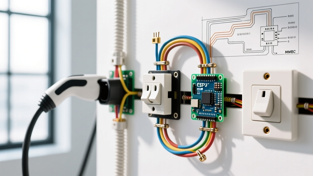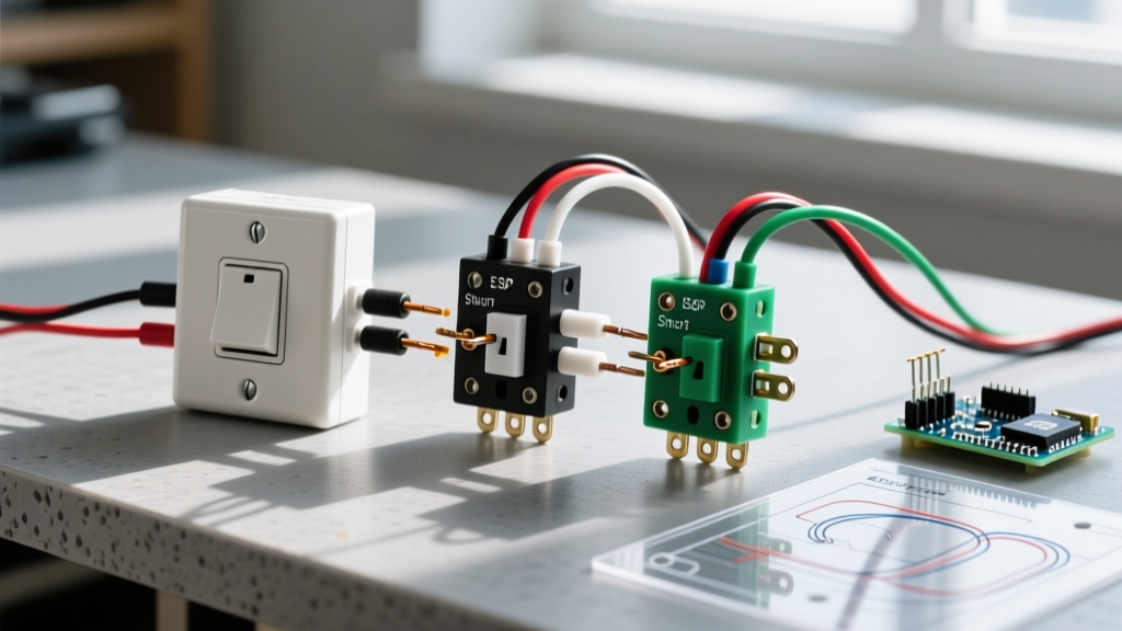

Decoding the Wiring Diagram for a Light Switch
Whether you are upgrading to a modern smart dimmer or replacing a burnt-out single-pole toggle, understanding the wiring diagram for a light switch is the most critical step in the process. A schematic is not just a suggestion; it is a precise map of electron flow, ensuring your circuit operates safely and complies with the latest National Electrical Code (NEC). In 2026, with the proliferation of smart home ecosystems and stricter energy mandates, switch wiring has evolved beyond simple make-or-break contacts.
This reference guide breaks down the anatomy of switch schematics, compares standard configurations, and provides actionable torque and termination specifications to prevent arc faults and thermal failures.
The Anatomy of a Switch Schematic
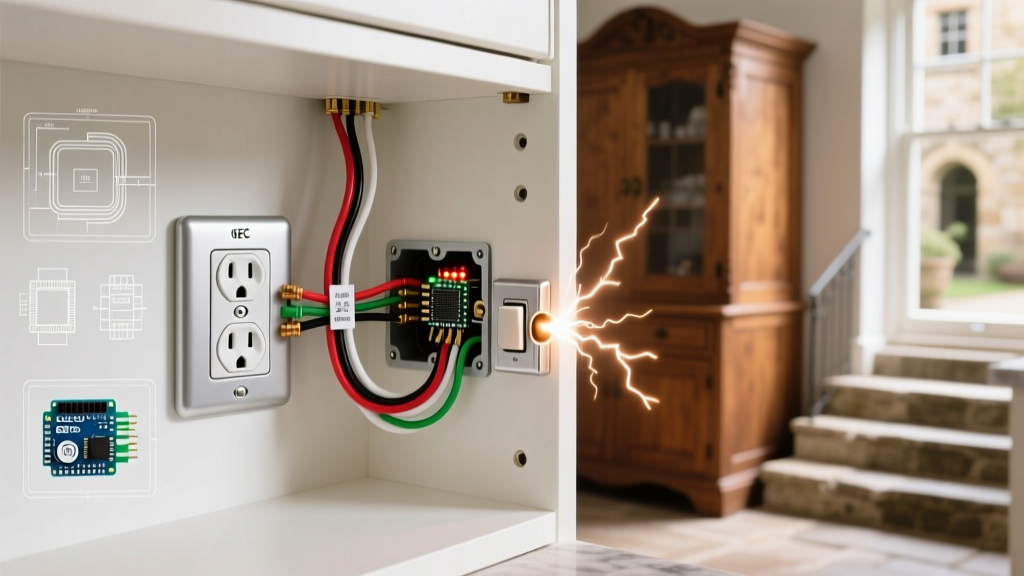
Before touching a wire stripper, you must understand the four primary conductors represented in any professional wiring diagram for a light switch:
- Line (Hot): The ungrounded conductor bringing 120V from the breaker panel. Typically insulated in black or red.
- Load: The ungrounded conductor carrying 120V from the switch to the light fixture.
- Neutral: The grounded conductor (white or gray) completing the circuit back to the panel. Note: Standard mechanical switches do not connect to the neutral, but smart switches require it.
- Ground: The equipment grounding conductor (bare copper or green), providing a safe path for fault currents.
NEC 2026 Code Alert: Under NEC Article 404.2(C), switch boxes controlling lighting loads must now have a neutral conductor available, even if the current switch does not use it. This mandates the use of 14/3 or 12/3 Romex in new construction switch loops to support future smart devices. Always verify local amendments via the National Fire Protection Association (NFPA).
Switch Configuration Comparison Matrix
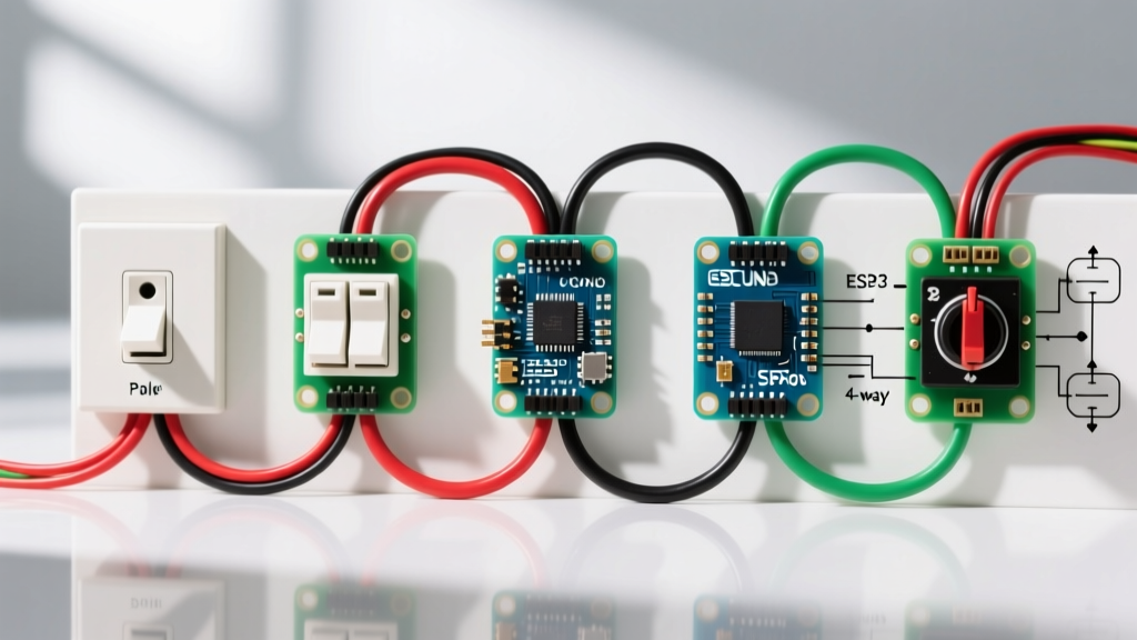
Not all switches are wired identically. The table below contrasts the three most common residential switch types you will encounter in schematics.
| Switch Type | Terminals Required | Cable Standard | Primary Application | Avg. Cost (2026) |
|---|---|---|---|---|
| Single-Pole | 2 Brass, 1 Green | 14/2 or 12/2 NM-B | Controlling a light from one location | $2.50 - $8.00 |
| 3-Way | 1 Black (Common), 2 Brass (Travelers), 1 Green | 14/3 or 12/3 NM-B | Controlling a light from two locations (e.g., staircases) | $8.00 - $18.00 |
| Smart Switch (Wi-Fi/Z-Wave) | Line, Load, Neutral, Ground | Requires Neutral in Box | App-controlled lighting, automation, scheduling | $25.00 - $65.00 |
Step-by-Step: Wiring a Single-Pole Switch
The single-pole switch is the foundational circuit in residential wiring. The wiring diagram for a light switch of this type is straightforward: the hot wire breaks the circuit to the load.
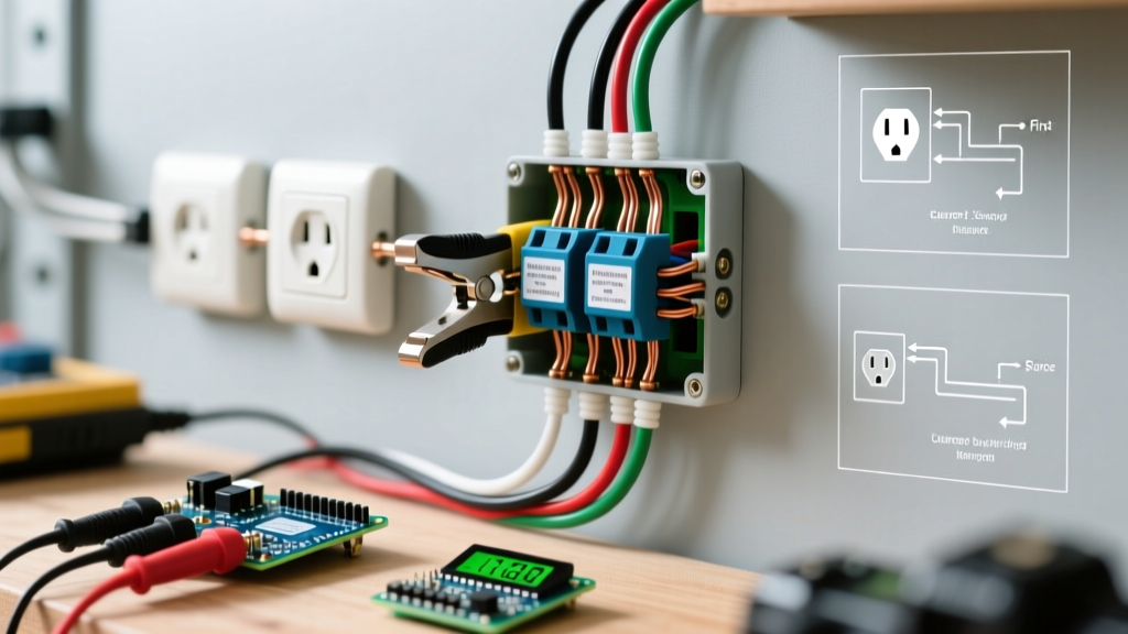
- Power Verification: Use a dual-range non-contact voltage tester (like the Klein Tools NCVT-41) to confirm the circuit is dead. Test on a known live circuit first to verify the tool's battery.
- Wire Preparation: Strip exactly 3/4 inch of insulation from the 14 AWG or 12 AWG solid copper conductors. Stripping too little exposes the screw to the insulation; stripping too much leaves bare, live copper exposed outside the terminal.
- Termination: Form a clockwise 'J-hook' with your needle-nose pliers. Hook the wire around the brass terminal screw so that tightening the screw pulls the loop closed, rather than pushing it out.
- Torque Specification: This is where most DIYers fail. According to Leviton's technical bulletins, standard 15A/20A residential switch terminal screws require a tightening torque of 14 in-lbs. Use a calibrated torque screwdriver (e.g., Klein Tools 32500) to prevent under-tightening (which causes arcing and heat) or over-tightening (which strips the brass threads).
- Grounding: Attach the bare copper ground wire to the green grounding screw. If the box is metal, you must also bond the box using a grounding pigtail.
Deciphering the 3-Way Switch Diagram
A 3-way switch schematic introduces 'traveler' wires. Unlike a single-pole switch, a 3-way switch does not have an 'ON' or 'OFF' printed on the toggle. Instead, it features one Common terminal (usually a darker, blackened screw) and two Traveler terminals (brass screws).
The Traveler Logic
In a standard 3-way wiring diagram for a light switch, the Line (Hot) connects to the Common terminal on Switch A. The Load connects to the Common terminal on Switch B. The two Traveler terminals on Switch A are connected directly to the two Traveler terminals on Switch B via a 3-wire cable (14/3). Toggling either switch changes the continuity path between the travelers, completing or breaking the circuit.
Pro-Tip: Always use colored electrical tape (e.g., yellow or blue) to mark the traveler wires at both ends. This prevents catastrophic confusion when troubleshooting or replacing the switches years later.
Smart Switches and the Neutral Wire Dilemma
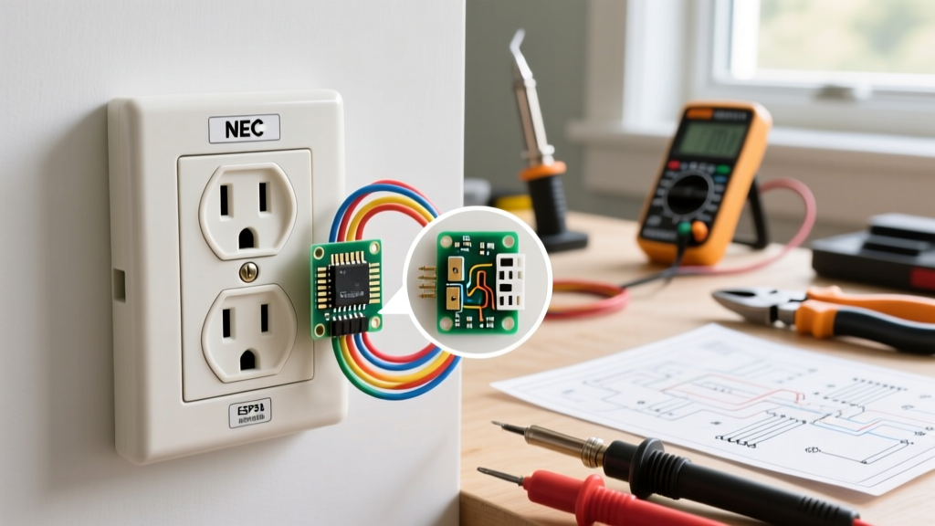
When transitioning from a mechanical toggle to a smart switch (like the Lutron Caseta PD-6WCL or TP-Link Kasa KS220), the wiring diagram changes significantly. Smart switches contain internal radios (Wi-Fi, Zigbee, or Lutron's Clear Connect) and microprocessors that require continuous standby power.
- Neutral-Required Switches (e.g., Kasa KS220): These connect to Line, Load, Neutral, and Ground. The internal circuit bridges Line and Neutral to power the Wi-Fi chip, while an internal relay switches the Load. If your switch box lacks a neutral (common in pre-1980s homes), you cannot use these.
- Neutral-Free Switches (e.g., Lutron PD-6WCL): These are engineered to trickle a tiny amount of current (less than 1mA) through the LED bulb itself to power the internal radio when the light is 'off.' They only require Line, Load, and Ground. However, they are strictly limited to lower wattages (typically 150W of LED) and require specific bulb compatibility to prevent flickering or ghosting.
Common Wiring Diagram Failures and Troubleshooting
Even with a correct schematic, physical installation errors occur. Here is how to diagnose the most frequent edge cases:
1. The 'Switched Neutral' Hazard
If a previous homeowner wired the switch to break the neutral wire instead of the hot wire, the light will turn off, but the fixture remains energized at 120V. This is a severe shock hazard. Always verify with a multimeter: with the switch OFF, probe the fixture's hot terminal to ground. If you read 120V, your switch is on the neutral leg and must be rewired immediately.
2. Backstabbing vs. Side Wiring
Many modern switches feature 'backstab' push-in terminals. While permitted by UL, industry experts and the Occupational Safety and Health Administration (OSHA) guidelines on electrical safety heavily discourage them for high-load circuits. The internal spring-loaded contacts can loosen over time due to thermal expansion and contraction, leading to high-resistance connections, melting, and arc faults. Always use the side-binding screw terminals.
3. Box Fill Violations
When adding smart switches or pigtailing grounds, you must calculate box fill per NEC Article 314.16. A standard single-gang plastic box is typically 18 to 22 cubic inches. Each 14 AWG wire counts as 2.0 cubic inches, and the switch device itself counts as 4.0 cubic inches. Cramming a bulky Wi-Fi smart switch into an 18-cubic-inch box with four 12 AWG wires will physically crush the conductors, risking insulation failure.
4. Phantom Voltage and LED Ghosting
When installing LED fixtures on older 3-way switch diagrams, you may notice the bulbs glowing faintly when turned off. This 'ghosting' occurs due to capacitive coupling between the ungrounded traveler wires running parallel in the 14/3 cable. The high impedance of LED drivers allows this induced millivoltage to charge the internal capacitors. The fix is not a new switch, but rather installing a high-wattage incandescent dummy load or a specialized LED ghosting resistor (like the Lutron LUT-MLC) across the Line and Load at the fixture to bleed off the phantom voltage.
Final Safety Protocols
A wiring diagram for a light switch is only as safe as the environment in which it is installed. In 2026, AFCI (Arc-Fault Circuit Interrupter) protection is mandated for virtually all 120V, 15A, and 20A branch circuits supplying lighting in dwelling units. If your new switch trips the AFCI breaker immediately upon closing, you likely have a shared neutral, a damaged wire insulation pinched inside the metal box, or a loose termination causing a parallel arc. Never bypass an AFCI breaker; trace the fault using a megohmmeter or consult a licensed electrician.