
Decoding the Electric EZGO Ignition Switch Wiring Diagram
When your electric EZGO golf cart refuses to start and the solenoid fails to click, the ignition switch is often the first component under suspicion. However, blindly replacing parts without understanding the underlying circuit is a costly mistake. The electric EZGO ignition switch wiring diagram varies significantly depending on whether your TXT model utilizes a Series, DCS, or PDS (Precision Drive System) controller. This comprehensive troubleshooting guide will walk you through the exact wiring architecture, terminal identification, and multimeter diagnostic procedures required to isolate the fault in 36V and 48V electric drivetrains.
System Architecture: Series vs. PDS Controllers
Before touching a multimeter, you must identify your controller type, as the key switch performs entirely different functions in each architecture:
- Series Motor Systems (Pre-2001): The ignition switch acts as a direct high-current routing valve. It takes full pack voltage from the solenoid's main input post and routes it directly to the solenoid's activation coil (S1 terminal). When you turn the key, you are physically sending 36V or 48V to the coil to close the heavy-duty contacts.
- PDS / DCS Systems (2001-2013): The ignition switch is a low-current logic trigger. Turning the key sends pack voltage to the 'Key Switch' input pin on the motor controller. The controller then wakes up, performs internal logic checks, and uses an internal transistor to provide the ground path for the solenoid coil.
Understanding this distinction is critical. In a PDS system, a lack of solenoid engagement with the key ON does not automatically mean the key switch is bad; it could indicate a controller logic fault or a faulty throttle microswitch preventing the controller from grounding the coil.
The Wiring Diagram Breakdown: 4-Post Heavy Duty Switch
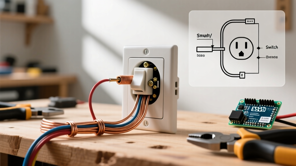
Most electric EZGO TXT models utilize a 4-post heavy-duty ignition switch (often replacing older 3-post variants for better load distribution). Here is the standard terminal mapping for the electric configuration:
- Terminal B (Battery / Input): Receives constant full pack voltage (36V or 48V). This wire typically originates from the large input post on the main solenoid or the main positive bus bar.
- Terminal S (Solenoid / Start): The primary output. In Series models, this routes directly to the solenoid's small activation post. In PDS models, this routes to the controller's key switch input harness.
- Terminal M (Motor / Accessory): Often used for accessory power (lights, horn, or radio). It provides switched power that only flows when the key is in the ON position.
- Terminal G (Ground): Used in specific illuminated key switch variants to complete the circuit for the LED or incandescent bezel light.
Expert Insight: Never confuse the gas EZGO ignition switch (which routes 12V to a starter solenoid and ignition coil) with the electric variant. Electric switches are rated for continuous DC duty and feature heavier internal copper contacts to handle the inductive loads of controller wake-up circuits.
Step-by-Step Multimeter Diagnosis
To accurately troubleshoot the circuit, you need a reliable digital multimeter (DMM). As outlined in Fluke's official multimeter guide, always verify your meter's functionality on a known live source before testing high-current DC circuits.
Step 1: Verify Pack Voltage State of Charge
Do not assume a 36V or 48V battery pack is outputting its nominal voltage. A depleted pack will prevent the controller from waking up, mimicking a bad ignition switch.
- 36V System (Fully Charged): Should read between 38.2V and 38.5V.
- 48V System (Fully Charged): Should read between 50.9V and 51.2V.
Connect your DMM's black probe to the main battery negative and the red probe to the Terminal B input wire on the back of the key switch. If you read 0V, your fault lies upstream (blown main fuse, corroded battery interconnects, or a tripped breaker), not in the switch itself.
Step 2: Key Switch Continuity and Output Testing
With the DMM set to DC Voltage, keep the black probe on a known good chassis ground or battery negative. Place the red probe on Terminal S.
- Key OFF: The meter should read 0V.
- Key ON: The meter should instantly jump to match the pack voltage (e.g., ~38.2V for a 36V cart).
If Terminal B has 38.2V but Terminal S reads 0V when the key is turned ON, the internal carbon contacts of the ignition switch have failed. The switch must be replaced.
Step 3: Voltage Drop Test Under Load
Sometimes a switch will pass a static voltage test but fail when asked to carry the 2 to 4 amps required to energize the solenoid coil. Switch your DMM to the DC Voltage setting. Place the red probe on Terminal B and the black probe on Terminal S. Turn the key ON. A healthy switch will show a voltage drop of less than 0.2V. If you see a drop of 2V or more, the internal contacts are pitted or suffering from carbon tracking, creating excessive resistance.
Diagnostic Matrix: Symptoms and Readings
| Cart Symptom | Probable Cause | Expected DMM Reading (Key ON) |
|---|---|---|
| Completely dead, no solenoid click | No input power to switch or main fuse blown | 0V at Terminal B |
| Dead, but dash accessories work | Switch output (Terminal S) failed open internally | Pack Voltage at B; 0V at S |
| Solenoid clicks, but cart won't move | Controller fault, bad F/R microswitch, or motor issue | Pack Voltage at both B and S |
| Intermittent starting, requires jiggling key | Melted Bakelite housing or worn internal rotary spring | Fluctuating voltage at S (drops under load) |
Edge Cases and Common Failure Modes
The 'Melted Housing' Phenomenon
In older TXT models, owners frequently install high-draw accessories (like 500W LED light bars or inverters) directly onto the ignition switch's accessory terminal without using a relay. The factory switch is typically rated for 15 to 20 amps maximum. Exceeding this causes the internal copper contacts to overheat, melting the surrounding Bakelite or plastic housing. If you notice a burnt smell or physical deformation around the key cylinder, replace the switch immediately and reroute accessory loads through a dedicated 12V converter and automotive relay.
PDS Controller 'Sleep Mode' Interference
On PDS models, the controller goes into a sleep mode to prevent battery drain. If the tow/run switch is in the 'TOW' position, the controller ignores the ignition switch entirely. Always verify the tow/run switch is in 'RUN' before diagnosing a dead PDS cart. For more complex controller logic faults, the enthusiast community at Buggies Gone Wild maintains extensive repositories of factory service manuals and wiring schematics for every production year.
Safety Protocols for DC Drivetrain Work
Working on 36V and 48V DC systems presents unique hazards. Unlike AC household current, DC current does not cross zero, meaning electrical arcs are sustained and can easily melt tools or cause severe burns. According to safety standards outlined by EZGO's official technical documentation and general DC electrical safety practices, you must always disconnect the main negative battery cable before removing or installing the ignition switch. Furthermore, ensure your replacement switch features integrated spark suppression or use an external diode across the solenoid coil to prevent inductive voltage spikes from destroying the new switch's internal contacts upon shutdown.
Sourcing the Right Replacement in 2026
When sourcing a replacement, avoid ultra-cheap unbranded switches found on generic marketplaces, which often use aluminum internal contacts instead of copper. Look for OEM-spec heavy-duty switches (typically ranging from $25 to $45 in 2026) that explicitly state compatibility with EZGO electric drivetrains. Ensure the physical bezel matches your dash panel (early TXT models use a different mounting nut thread pitch compared to the 2001+ Valor and PDS dashes).