
Understanding the GM Midsize Truck Platform
When truck enthusiasts and contractors search for the chevy colorado electrical outlet on canyon truck bed location, they are often navigating the shared architecture of General Motors' midsize truck lineup. The 3rd-generation Chevrolet Colorado and GMC Canyon (spanning the 2023 through 2026 model years) share the GMT32XX platform. This means their bed dimensions, electrical harnesses, and factory accessory locations are virtually identical. Whether you are driving a Chevy ZR2 or a GMC AT4, understanding where the factory power is located—and how to upgrade it for heavy-duty use—is critical for overlanding, job site tool charging, and camper setups.
Expert Insight: The factory 120V AC bed outlets on the Colorado and Canyon are typically limited to 400 watts. While sufficient for charging laptops or running small coolers, they will trip the internal inverter if you attempt to run a reciprocating saw, a heavy-duty air compressor, or a microwave. Upgrading to a dedicated pure sine wave inverter system is the only reliable solution for high-draw applications.
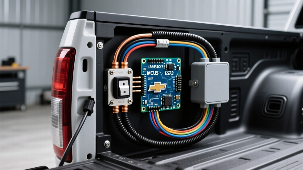
Factory Chevy Colorado Electrical Outlet on Canyon Truck Bed Location
Before tearing into the wiring, it is important to know where GM placed the factory receptacles. The exact location depends heavily on your trim level and whether you have the factory tow package or the technology package. Below is a breakdown of the factory outlet locations for the current generation trucks.
| Trim Level (Chevy / GMC) | Bed Outlet Location | Max Wattage / Amperage |
|---|---|---|
| WT / Pro (Base) | None (12V DC cigarette lighter in cab only) | N/A |
| LT / SLE | Driver-side bed wall, forward of wheel well | 120V AC / 400W (approx 3.3A) |
| Z71 / SLT | Driver-side bed wall & Rear center console | 120V AC / 400W |
| ZR2 / AT4 / Denali | Tailgate integrated & Driver-side bed wall | 120V AC / 400W |
For a comprehensive look at the factory specifications and wiring schematics for your specific VIN, you can always reference the official Chevrolet Colorado or GMC Canyon owner resources provided by GM.
Why Upgrade to an Aftermarket 120V Bed Outlet?
The factory 400W inverter is a modified sine wave unit tucked under the rear seats or behind the cab wall. It is prone to voltage sag and cannot handle the startup surge (inrush current) of inductive loads like power tool motors or air compressors. By installing an aftermarket 1000W+ Pure Sine Wave inverter and a marine-grade GFCI receptacle directly in the bed, you eliminate voltage drop over long factory wiring runs and gain the ability to run sensitive electronics and heavy tools safely.
Step-by-Step Installation: High-Capacity 120V Bed Receptacle
This installation requires intermediate electrical knowledge. We will be installing a Victron Phoenix 12/1200 Pure Sine Wave Inverter and routing 10 AWG marine-tinned wire to a Marinco Weatherproof GFCI receptacle mounted in the driver-side bed wall.
Phase 1: Preparation and Component Gathering
Before starting, disconnect the negative terminal on your truck's 12V battery. Gather the following components:
- Inverter: Victron Phoenix 12/1200 (approx. $280)
- Receptacle: Marinco 15A Marine GFCI with Weatherproof Cover (approx. $65)
- Wiring: 25 feet of 10 AWG Duplex Marine-Tinned Copper Wire (approx. $45)
- Protection: 40A ANL Fuse block with 40A fuse, 2/0 AWG battery cables
- Hardware: 3-inch hole saw, silicone sealant, adhesive-lined heat shrink, split loom tubing
Phase 2: Inverter Mounting and Primary Power
- Mount the Inverter: Secure the Victron inverter under the rear passenger seat or in a dedicated bed-mounted lockbox using the provided M8 flange nuts. Ensure at least 4 inches of clearance around the cooling fan.
- Run Battery Cables: Route the 2/0 AWG positive cable from the inverter to the engine bay battery. Crucial: Install the 40A ANL fuse within 18 inches of the battery positive terminal to comply with automotive electrical safety standards.
- Grounding: Attach the 2/0 AWG negative cable to a clean, bare metal point on the truck's chassis. Use a wire brush to remove paint and coat the terminal with dielectric grease to prevent corrosion.
Phase 3: Routing the 120V AC Wiring to the Bed
To maintain a clean look and protect the wiring from road debris, you must route the 10 AWG duplex wire through the frame rail.
- Drill a 1-inch hole in the floor pan or bed bulkhead near the inverter location. Install a rubber grommet to prevent the sheet metal from slicing the wire insulation.
- Feed the 10 AWG wire through the grommet and down into the undercarriage.
- Run the wire inside a split loom tubing along the inside of the driver-side frame rail, securing it every 12 inches with UV-resistant zip ties or aluminum P-clamps.
- Route the wire up through an existing drain hole or a newly drilled grommeted hole in the driver-side bed wall, positioning it just behind the factory outlet location (or in a clear, flat section of the bed sheet metal if your truck lacks the factory outlet).
Phase 4: Mounting and Wiring the GFCI Receptacle
Because a truck bed is classified as a wet and high-vibration environment, standard residential outlets will fail quickly due to moisture ingress and rattling. According to the National Electrical Code (NFPA) guidelines for wet locations, a GFCI (Ground Fault Circuit Interrupter) is mandatory for outdoor and damp receptacles.
- Cut the Hole: Use a 3-inch bi-metal hole saw to cut through the bed wall. Immediately paint the bare metal edges with cold galvanizing compound or rust-inhibiting primer to prevent oxidation.
- Seal the Box: Apply a generous bead of marine-grade silicone (like 3M 5200 or GE Silicone II) to the back of the Marinco weatherproof flange.
- Terminate the Wires: Strip the 10 AWG wire. Crimp on spade connectors using a heavy-duty ratcheting crimper. Slide adhesive-lined heat shrink over the crimps and apply heat until the adhesive oozes out, creating a waterproof seal.
- Connect to GFCI: Attach the Black (Hot) to the brass screw, White (Neutral) to the silver screw, and the bare ground to the green screw on the Marinco GFCI. Tighten to 14 in-lbs of torque.
- Secure the Cover: Mount the receptacle into the hole and secure the weatherproof bubble cover. Ensure the gasket is seated evenly.
Component Cost and Time Breakdown
| Item / Phase | Estimated Cost (2026 Pricing) | Time Required |
|---|---|---|
| Victron 1200W Inverter & Cables | $320.00 | 1.5 Hours |
| Marinco GFCI & 10 AWG Wiring | $110.00 | 1.5 Hours |
| Consumables (Silicone, Heat Shrink) | $25.00 | 0.5 Hours |
| Total Project | $455.00 | 3.5 Hours |
Troubleshooting Common Bed Outlet Failures
Even with a meticulous installation, the harsh environment of a truck bed can cause electrical gremlins. Here is how to diagnose the most common issues:
1. GFCI Trips Immediately Upon Plugging in a Tool
Cause: Moisture inside the receptacle box or a neutral-to-ground fault.
Fix: Remove the cover and inspect for condensation. Ensure the neutral (white) and ground (bare) wires are not touching anywhere downstream of the GFCI. If the truck bed was recently pressure washed, let the outlet dry completely and spray the internal terminals with CRC Di-Electric Grease.
2. Inverter Shuts Off Under Heavy Load (Low Voltage Alarm)
Cause: Voltage drop on the 12V DC side. The Victron inverter requires a solid 12.5V+ to operate at 1200W. If your battery cables are too long or undersized, the voltage at the inverter drops below 10.5V under load, triggering the safety cutoff.
Fix: Verify you are using 2/0 AWG cables for runs over 5 feet. Clean the chassis ground point. Consider adding a secondary deep-cycle AGM or LiFePO4 battery in the bed to act as a buffer for high-surge tools.
3. Receptacle Rattles and Loosens Over Time
Cause: The thin sheet metal of the truck bed flexes during off-road driving, causing the mounting screws to wallow out the hole.
Fix: Remove the receptacle and install a stainless steel backing plate behind the bed wall. Use stainless steel machine screws with nylon-insert lock nuts (nyloc nuts) instead of sheet metal screws to secure the outlet permanently.
Final Safety and Compliance Checks
Before reconnecting the truck's battery and powering up the system, double-check all crimp connections with a multimeter for continuity and ensure no stray copper strands are bridging the hot and neutral terminals. When working with mobile power systems, adhering to standards set by organizations like the American Boat & Yacht Council (ABYC) for marine wiring is highly recommended, as truck beds face similar moisture and vibration challenges as marine environments. By following this guide, your Chevy Colorado or GMC Canyon will be equipped with a robust, job-site-ready 120V power source that far outperforms the factory limitations.