
The Hidden Dangers of a Cracked Electrical Outlet
A cracked electrical outlet is rarely just a cosmetic issue. While a hairline fracture on the faceplate might seem trivial, it often indicates underlying structural degradation, thermal stress, or physical trauma that compromises the receptacle's internal geometry. In 2026, with household electrical loads higher than ever due to smart home hubs, EV chargers, and high-draw appliances, the integrity of your wall receptacles is a critical fire safety boundary.
According to the Electrical Safety Foundation International (ESFI), electrical distribution and lighting equipment consistently rank among the top causes of residential fires. A compromised receptacle housing can allow moisture ingress, dust accumulation, and physical shifting of the internal brass and silver contacts, leading to arc faults or high-resistance connections. This inspection and testing guide will walk you through professionally diagnosing a damaged receptacle, testing its electrical viability, and executing a code-compliant replacement.
Material Science: Why Do Outlet Plastics Crack?
To properly inspect a damaged outlet, you must understand the materials involved. Standard residential receptacles are typically molded from thermoplastics like Polycarbonate (PC) or Polybutylene Terephthalate (PBT). Commercial-grade models often use high-impact Nylon. Cracks generally originate from three specific failure modes:
- Thermal Cycling Fatigue: Repeatedly drawing near-maximum current (e.g., 12A to 15A on a 15A circuit) causes the internal brass contacts to heat up. This heat transfers to the plastic housing, causing microscopic expansion and contraction that eventually leads to stress fractures.
- Yoke Over-Torquing: If the drywall cutout is too tight or uneven, electricians or DIYers may over-tighten the 6-32 mounting screws. This bends the metal mounting yoke, placing immense lateral tension on the brittle thermoplastic face until it snaps.
- UV and Ozone Degradation: Outlets in sunrooms, garages, or outdoor enclosures (even with weather covers) can suffer from UV embrittlement, turning flexible PBT into a brittle shell that shatters upon physical impact, such as a vacuum cleaner cord being yanked.
Phase 1: Visual and Physical Inspection Protocol
Before touching any testing equipment, perform a rigorous visual and physical inspection. Safety first: ensure the circuit breaker is turned off at the main panel and verify the absence of voltage using a dual-range Non-Contact Voltage Tester (NCVT), such as the Klein Tools NCVT-2.
1. Faceplate and Housing Assessment
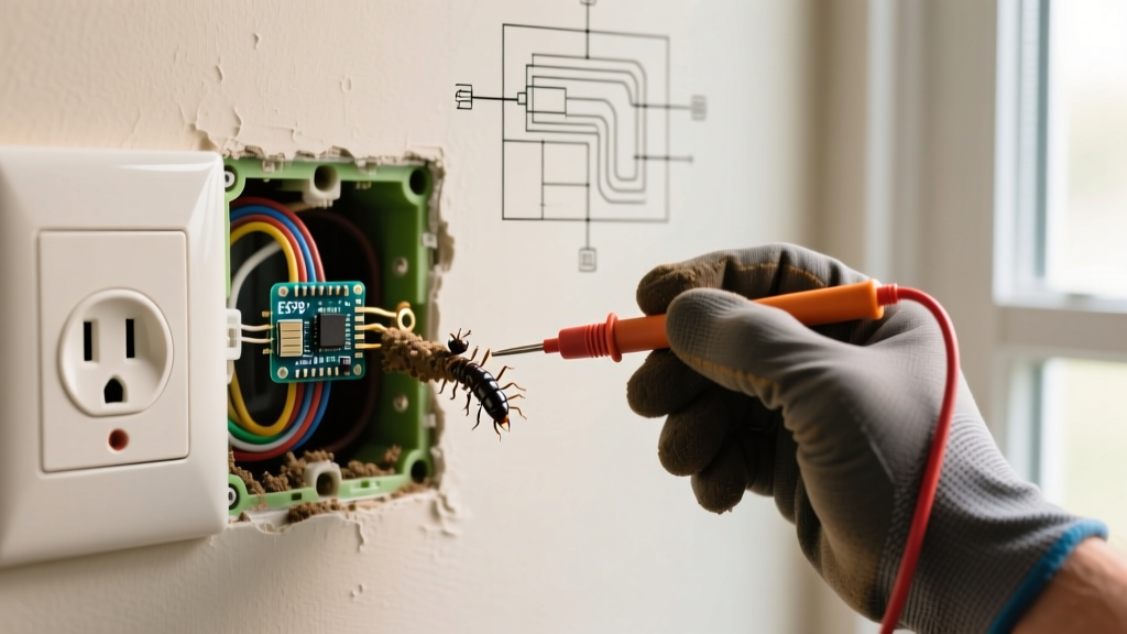
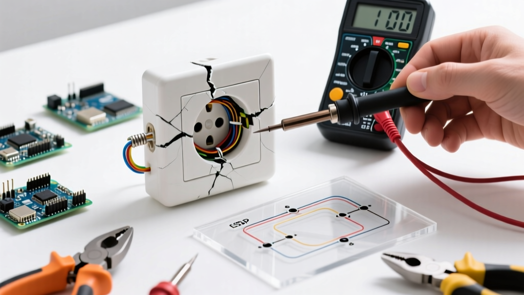
Remove the decorative wall plate. Inspect the thermoplastic housing of the receptacle itself. Look for hairline fractures radiating from the mounting screw holes or the receptacle slots. If the crack exposes the internal brass terminals or the grounding strap, the device is an immediate shock hazard and must be replaced.
2. Yoke and Mounting Integrity
Gently attempt to wiggle the receptacle. A properly installed outlet should be rock solid. If the receptacle shifts inward or rotates, the internal yoke may be warped, or the drywall ears may have snapped off. A loose receptacle causes plug blades to lose contact pressure, creating micro-arcing every time a device is plugged in or switched on.
3. Internal Shutter Mechanism (TR Receptacles)
Modern code requires Tamper-Resistant (TR) shutters. Inspect the plastic shutters inside the slots. If the external housing is cracked, the alignment of these internal shutters is often compromised, causing plugs to jam or forcing users to apply excessive pressure, which further damages the internal contacts.
Phase 2: Electrical and Thermal Diagnostics
If the crack appears superficial (e.g., a minor scratch or edge chip) and you are attempting to determine if the outlet is still electrically safe to leave in service temporarily, you must perform electrical and thermal testing. Note: The Consumer Product Safety Commission (CPSC) strongly recommends replacing any structurally compromised electrical device rather than attempting to validate its continued use.
Multimeter Termination Testing
Using a True-RMS digital multimeter (such as the Fluke 117), test the circuit under load to check for voltage drops that indicate a failing internal connection exacerbated by the cracked housing.
- Restore power to the circuit.
- Plug in a known high-draw resistive load (e.g., a 1500W space heater or hair dryer) into the other socket on the same duplex receptacle or a downstream outlet.
- Set your multimeter to V AC.
- Measure Line (Brass) to Neutral (Silver) at the cracked receptacle's slots. A reading below 114V (on a nominal 120V circuit) while under load indicates high resistance in the terminations or internal bus bars.
- Measure Line to Ground (Green). It should read identically to Line to Neutral (+/- 0.5V).
Thermal Imaging Diagnostics
High-resistance connections generate heat. Using a compact thermal camera like the FLIR C5, scan the cracked outlet while it is under a minimum 10A load. If the thermogram reveals a delta-T (temperature difference) of greater than 10°C (18°F) between the receptacle face and the ambient wall temperature, the internal connections are failing. A cracked housing accelerates this failure by allowing ambient dust to settle on the heated brass, creating a carbon track that can eventually lead to an arc flash.
Crack Severity and Risk Matrix
Use the following matrix to determine your immediate course of action based on the location and nature of the crack.
| Crack Location | Severity Level | Primary Risk | Required Action |
|---|---|---|---|
| Faceplate edge (cosmetic) | Low | Dust ingress, aesthetic | Monitor; replace during next room upgrade |
| Mounting screw hole / Yoke area | High | Device shifting, arcing, shock | Immediate replacement; inspect drywall box |
| Between Line/Neutral slots | Critical | Short circuit, TR shutter failure | De-energize circuit immediately; replace |
| Internal housing (visible through slots) | Critical | Fire, arc fault, electrocution | De-energize circuit immediately; replace |
Phase 3: Safe Replacement and 2026 Code Compliance
If your inspection dictates replacement, do not simply swap in the cheapest builder-grade receptacle available. The 2026 National Electrical Code (NEC) continues to strictly enforce the use of Tamper-Resistant (TR) receptacles in all dwelling unit areas, as highlighted by ESFI's ongoing safety campaigns.
Selecting the Right Replacement Receptacle
For standard residential 15A circuits (14 AWG or 12 AWG wire), you have two primary tiers of replacement options:
- Residential Grade (e.g., Leviton T5262-W): Priced around $3.50 to $4.50 in 2026. Features standard thermoplastic construction and side-wiring with internal back-wire clamps. Suitable for bedrooms and living areas.
- Commercial/Spec Grade (e.g., Hubbell 5262 or Leviton 5262): Priced between $8.00 and $12.00. Features high-impact Nylon faces, thicker brass contacts, and a reinforced steel yoke. Highly recommended for high-traffic areas, kitchens, and locations where physical impact (vacuum cleaners, furniture) caused the original crack.
Termination and Torque Specifications
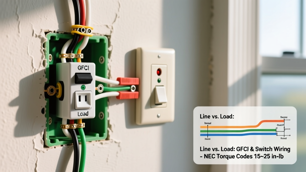
A major cause of outlet cracking and subsequent fire hazards is improper termination. NEC Section 110.14(D) mandates the use of a calibrated torque tool for all electrical terminations.
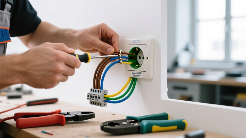
Expert Tip: Do not use the 'back-stab' push-in holes on the rear of 15A receptacles. These rely on a small spring-metal grip that loosens over time under thermal cycling. Always use the side terminal screws or the internal back-wire clamp plates. For a standard Leviton 15A TR receptacle, the manufacturer-specified torque for the terminal screws is exactly 14 in-lbs. Use an insulated torque screwdriver, such as the Klein Tools 32500 series, to ensure precise tension without cracking the new housing.
Addressing the Root Cause: Shimming and Box Leveling
If the original outlet cracked due to yoke tension from uneven drywall, you must correct the mounting surface before installing the new device. Use plastic receptacle shims (e.g., Caddy TS100) behind the mounting ears to bridge the gap between the electrical box and the drywall. This ensures the mounting screws pull the yoke straight back without bending it, eliminating the lateral stress that causes thermoplastic housings to fracture.
Frequently Asked Questions (FAQ)
Can I use electrical tape to cover a cracked outlet?
No. Electrical tape is a temporary insulator, not a structural repair material. Taping over a cracked outlet does not restore the physical alignment of the internal TR shutters or the brass contacts. Furthermore, tape can trap heat generated by the receptacle, increasing the risk of thermal degradation and fire. Always replace the device.
Does a cracked GFCI outlet pose a different risk than a standard outlet?
Yes. A Ground Fault Circuit Interrupter (GFCI) contains complex internal solid-state circuitry and a sensing coil. If the housing of a GFCI is cracked, moisture or conductive dust can easily breach the enclosure and short out the sensing circuitry. This can cause the GFCI to fail silently, leaving you without ground-fault protection in wet areas like bathrooms or garages. Replace cracked GFCIs immediately.
How often should I inspect my wall outlets for damage?
Homeowners should perform a visual inspection of all accessible outlets and switches annually. Look for discoloration (brown or black scorch marks), physical cracks, loose-fitting plugs, and unusual warmth when touching the faceplate. Any outlet exhibiting these signs should be tested with a multimeter and replaced if necessary.