
Understanding the Terminology: Plug vs. Receptacle
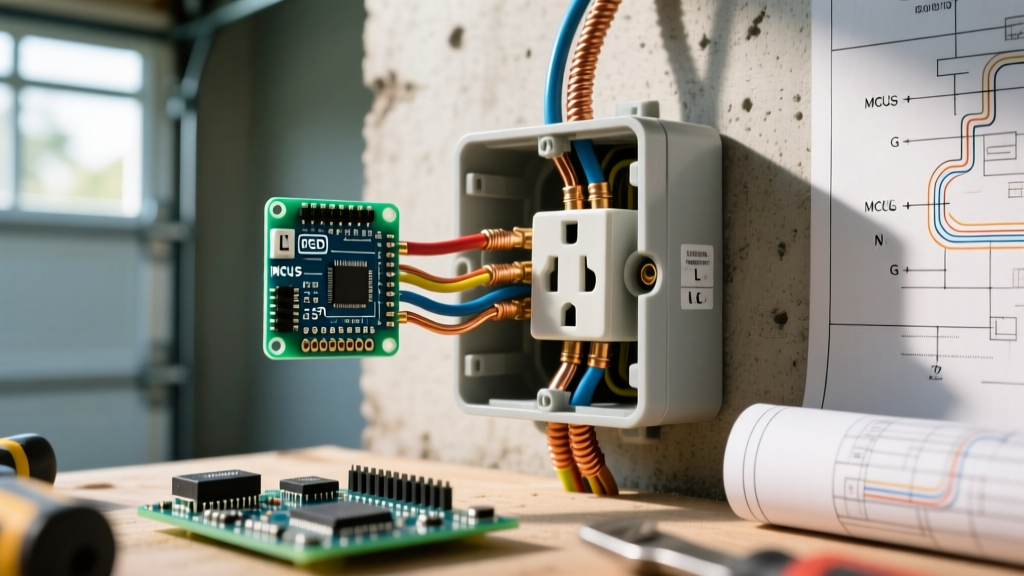
While the phrase wiring a electrical plug is commonly used in DIY searches, the National Electrical Code (NEC) draws a strict, legally binding line between the components involved in an electrical connection. Before stripping a single wire, it is critical to understand the terminology defined in NEC Article 100. A receptacle is the female contact device installed in the wall box (commonly called an outlet). An attachment plug is the male connector attached to the flexible cord of an appliance.
Confusing these terms can lead to purchasing the wrong replacement parts, misapplying code articles, and creating severe fire hazards. This guide breaks down the exact NEC requirements for wiring both wall receptacles and male attachment plugs, ensuring your installation meets the rigorous safety standards expected by licensed electricians and local inspectors in 2026.
Core Receptacle Wiring Mandates (NEC Articles 210 & 406)
When wiring a standard 15A or 20A duplex receptacle, the NEC mandates strict adherence to polarity, grounding continuity, and conductor identification. Violating these rules is not just a technical foul; it creates lethal shock hazards and equipment damage risks.
1. Polarity and Terminal Identification
NEC Section 200.7 and 210.5 dictate that the grounded conductor (neutral) must be connected to the silver-colored terminal, while the ungrounded conductor (hot) connects to the brass-colored terminal. Reversing this polarity means the internal switch of a plugged-in appliance might only interrupt the neutral path, leaving the appliance's internal components energized at 120V even when turned off. Always use a non-contact voltage tester and a plug polarity checker after terminating the wires.
2. Grounding Continuity and Pigtailing
One of the most frequently cited code violations during inspections involves daisy-chaining ground wires through the receptacle's green grounding screw. Under NEC 250.148, the grounding path must remain continuous. If you rely on the receptacle's internal yoke to pass the ground to downstream devices, removing that single receptacle breaks the ground path for everything downstream. The code-compliant method is to use a wire nut to join the incoming ground, the outgoing ground, and a 6-inch pigtail that connects to the receptacle's green screw.
Wiring Attachment Plugs: The Male Cord End
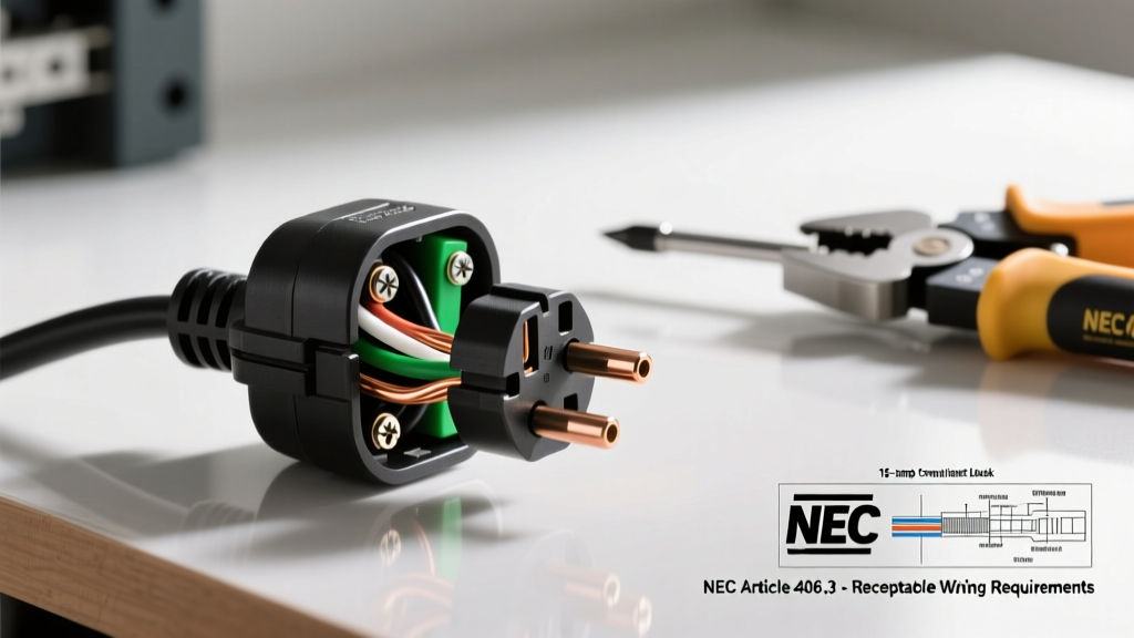
If your project specifically involves wiring an attachment plug (replacing a damaged male cord end on a power tool or appliance), you must follow NEC Article 400 (Flexible Cords and Cables) and NEMA WD6 dimensional standards. The most critical safety feature of an attachment plug is the strain relief mechanism.
Strain Relief and Cord Grip Requirements
NEC 400.10 strictly prohibits using the terminal screws to hold the mechanical weight of the cord. Every replacement plug must feature an internal cord grip that clamps down on the outer insulation jacket of the flexible cord, not the individual copper conductors. If the cord grip fails to secure the jacket, any tug on the cord will pull the hot or neutral wires off their terminals, potentially causing a short circuit inside the plug housing.
| NEMA Configuration | Ampacity / Voltage | Grounding | Common Application |
|---|---|---|---|
| NEMA 1-15P | 15A / 125V | Ungrounded (2-Prong) | Legacy lamps, double-insulated vintage tools (No longer permitted for new branch circuits) |
| NEMA 5-15P | 15A / 125V | Grounded (3-Prong) | Standard household appliances, AV equipment, power supplies |
| NEMA 5-20P | 20A / 125V | Grounded (T-Slot Neutral) | Heavy-duty shop vacuums, commercial kitchen equipment, window AC units |
| NEMA L5-15P | 15A / 125V | Grounded (Twist-Lock) | Generators, temporary construction site lighting, stage equipment |
The Hidden Code: Torque Specifications (NEC 110.14)
Historically, electricians tightened terminal screws by 'feel.' However, loose connections cause high-resistance arcing, leading to thermal expansion, melting, and electrical fires. To combat this, the NEC introduced Section 110.14(D), which mandates that terminations must be tightened to the torque values specified by the manufacturer.
Expert Insight: For commercial-grade 15A and 20A receptacles (such as the Leviton 5362 or Hubbell HBL5362), the manufacturer-specified torque is typically 14 inch-pounds (in-lbs). Residential-grade devices often specify 12 to 14 in-lbs. Using a calibrated torque screwdriver (like the Klein Tools 32500 series) is no longer optional for professionals and is highly recommended for serious DIYers to prevent callback failures and pass strict municipal inspections.
Box Fill Calculations: Don't Overcrowd the Junction
When wiring a receptacle, the physical space inside the electrical box matters just as much as the wire connections. NEC Article 314.16 outlines box fill calculations to prevent wires from being crushed, which can compromise insulation and cause ground faults.
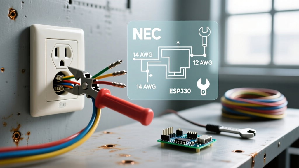
- Conductor Volumes: Each 14 AWG wire requires 2.0 cubic inches of space; each 12 AWG wire requires 2.25 cubic inches.
- Device Yoke Allowance: A standard duplex receptacle counts as two conductor volumes based on the largest wire connected to it. If you are using 12 AWG wire, the receptacle itself consumes 4.5 cubic inches of box fill.
- Clamps and Grounds: Internal cable clamps count as one volume. All grounding wires combined count as a single volume based on the largest ground wire present.
If you are upgrading a circuit to 12 AWG wire on a 20A breaker, ensure you are using deep junction boxes (minimum 22.5 cubic inches for a single receptacle with multiple feed-through cables) rather than standard shallow 16-cubic-inch boxes.
GFCI and AFCI Protection Mandates
The NEC continuously expands its requirements for Ground Fault Circuit Interrupter (GFCI) and Arc Fault Circuit Interrupter (AFCI) protection. According to OSHA and NEC safety guidelines, GFCI protection (NEC 210.8) is mandatory for all 125V, 15A, and 20A receptacles installed in kitchens, bathrooms, garages, outdoors, crawl spaces, unfinished basements, laundry areas, and within 6 feet of any sink or wet bar.
Furthermore, NEC 210.12 requires AFCI protection for nearly all living spaces, including bedrooms, living rooms, and hallways, to detect dangerous parallel and series arcing conditions that standard breakers cannot see. When wiring a receptacle in these zones, you must either install an AFCI/GFCI dual-function breaker in the main panel or use a combination GFCI receptacle at the first point of the circuit to feed through to downstream standard receptacles.
Terminal Connections: Screw vs. Push-In (Backstab)
Many modern receptacles feature push-in (backstab) terminals on the rear. While UL-listed for use, NEC 110.14 requires connections to be 'suitable for the use.' Most manufacturer instructions strictly limit push-in terminals to 14 AWG solid copper wire only. They cannot be used with 12 AWG wire, nor can they be used with stranded wire.
Moreover, industry failure analysis shows that push-in terminals rely on a small internal spring-steel wedge. Over years of thermal cycling (heating under load and cooling when off), these springs can lose tension, leading to high-resistance connections and melted plastic housings. Best Practice: Always use the side-wire screw terminals. Loop the stripped wire clockwise around the screw so that tightening the screw pulls the loop tighter. Strip exactly 3/4 inch of insulation using the built-in gauge on the receptacle yoke to ensure no bare copper is exposed outside the terminal housing.
Summary of Best Practices for 2026 Installations
- Verify Wire Gauge: Match 14 AWG to 15A breakers/receptacles and 12 AWG to 20A circuits.
- Use Pigtails: Never daisy-chain neutrals or grounds through the device yoke.
- Torque to Spec: Use a torque screwdriver set to 14 in-lbs for commercial devices.
- Test Before Energizing: Verify polarity and GFCI trip functionality with a digital circuit analyzer before securing the faceplate.