
Decoding the 7.3L Power Stroke High-Amperage Contactor
When dealing with heavy-duty diesel electrical systems, the glow plug relay (GPR) is one of the most critical high-current switching components. For the Ford 7.3L Power Stroke (1994–2003), the GPR acts as a massive DC contactor, bridging the gap between low-amperage computer logic and the extreme amperage required to heat ceramic glow plugs. Understanding the wiring diagram for glow plug relay 7.3 configurations is essential for diagnosing hard-start conditions, parasitic draws, and melted harness pigtails. Unlike standard 12V automotive relays that handle 30A to 40A, the 7.3L GPR must manage initial inrush currents exceeding 150A, settling into a steady state of roughly 80A to 100A. In the realm of high-amperage switching scenarios, treating this component with the same respect as an industrial HVAC contactor or a heavy-duty solar solenoid is vital for safety and reliability.
Safety Warning: The large terminals on the 7.3L GPR carry constant, unfused battery voltage directly from the starter solenoid or battery junction box. Always disconnect the negative battery terminals before removing the terminal nuts. An accidental short to the valley tray or engine block with a wrench will instantly weld the tool, melt the wiring harness, and pose a severe arc-flash and fire hazard.
Terminal Pinout: The Wiring Diagram for Glow Plug Relay 7.3
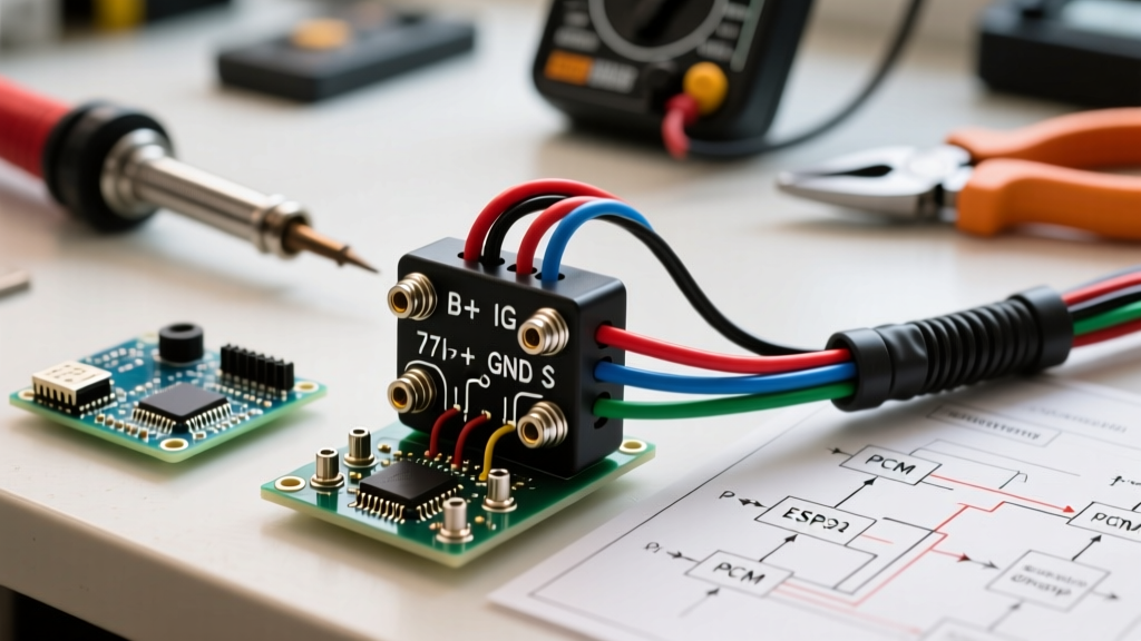
The physical relay used in the 7.3L Power Stroke typically features four terminals: two large threaded studs for the load circuit and two smaller spade or connector pins for the control coil. Below is the definitive breakdown of the terminal assignments based on the standard Motorcraft SWD-611 (Early OBS) and SWD-612 (Super Duty) architectures.
| Terminal | Wire Gauge / Type | Function | Voltage / Amperage |
|---|---|---|---|
| Large Stud 1 (Input) | 2 AWG to 4 AWG | Constant 12V Battery Feed | 12.6V / 0A (Static) |
| Large Stud 2 (Output) | 4 AWG to 6 AWG | Switched Output to Glow Plug Bus Bars | 12.6V / 100A+ (Active) |
| Small Pin 1 (Coil +) | 16 AWG to 18 AWG | Switched 12V from PCM Power Relay | 12V / ~1.5A |
| Small Pin 2 (Coil -) | 16 AWG to 18 AWG | PCM Ground Trigger (Low-Side Switch) | 0V (when PCM pulls to ground) |
Control vs. Load: How the PCM Manages the Switch
To truly master the wiring diagram for glow plug relay 7.3 applications, you must separate the control circuit from the load circuit. The Powertrain Control Module (PCM) does not directly power the relay coil; instead, it uses a low-side switching strategy. For a deeper understanding of how electromagnetic coils function in low-side switching configurations, refer to the foundational relay theory outlined by All About Circuits.
The Coil Side (Control Circuit)
When you turn the key to the 'ON' position, the PCM power relay energizes, sending 12V to one of the small terminals on the GPR. The PCM then monitors the Engine Oil Temperature (EOT) sensor. If the EOT is below approximately 130°F (54°C), the PCM completes the circuit by internally grounding the second small terminal. This energizes the electromagnetic coil, pulling the heavy internal copper contactor downward to bridge the two large studs. The PCM will hold this ground for anywhere from 5 seconds to 120 seconds, depending on ambient temperature and battery voltage, or until the alternator begins charging above 13.0V.
The Contact Side (Load Circuit)
The load side is a brute-force DC circuit. The constant 12V feed originates from the passenger-side battery positive terminal (or the starter solenoid mega-fuse distribution point) and travels through a heavy-gauge cable to the input stud. When the coil is energized, the internal contactor bridges the gap, sending massive current down into the engine valley, where it splits to the left and right glow plug bus bars. As detailed in Littelfuse application notes on high-current DC circuits, managing the inrush current and preventing contact pitting is the primary engineering challenge in these load circuits.
Diagnostic Scenarios: Testing the Relay Under Load
A common mistake among DIY mechanics is testing the GPR with the engine off and no load applied. A relay with severely pitted internal contacts might show 12V on a multimeter when the circuit is open, but under the 100A load of eight glow plugs, the voltage will collapse. Here is how to properly diagnose the wiring and relay health:
- The Voltage Drop Test (Crucial): Set your Digital Multimeter (DMM) to DC Volts. Place the red probe on the large input stud and the black probe on the large output stud. Have an assistant turn the key to the 'ON' position to activate the relay. A healthy relay and clean wiring will show a voltage drop of less than 0.1V. If you see a drop of 0.5V to 2.0V or higher, the internal contacts are burned, or the terminal nuts are corroded.
- Coil Resistance Check: Disconnect the small control wires. Measure the resistance across the two small coil pins. A healthy coil should read between 10 and 15 ohms. A reading of infinite (OL) indicates a burned-out internal coil winding.
- Bus Bar Continuity: If the relay clicks and outputs 12V, but the engine still won't start in the cold, the issue is often the wiring harness from the relay to the valve cover gaskets. Check for chafing where the harness rubs against the valley fuel filter housing.
Upgrading to the White-Rodgers 586-902
The OEM Motorcraft relays are notorious for premature contact pitting, often failing within 60,000 to 80,000 miles. The industry-standard upgrade for the 7.3L Power Stroke is the White-Rodgers 586-902 (often sold under the Stancor brand). Priced between $45 and $65 in 2026, this continuous-duty solenoid features a heavier copper contactor, a more robust coil, and superior arc suppression. For more on electromagnetic switching mechanisms, Electronics Tutorials provides excellent schematics on contactor arc quenching.
- Disconnect Batteries: Remove the negative cables from both the driver and passenger side batteries to eliminate all potential ground paths.
- Remove OEM Relay: Use a 10mm or 5/16-inch wrench to remove the nuts on the large studs. Carefully note the orientation of the small control wires (though the coil is non-polarized, keeping the harness untwisted prevents strain).
- Clean Terminals: Use a wire brush and electrical contact cleaner on the heavy-gauge ring terminals. Apply a thin layer of di-electric grease to the threads to prevent future corrosion.
- Install 586-902: Mount the new relay. Torque the large terminal nuts to approximately 85 in-lbs. Warning: Do not over-torque, as you can snap the internal threaded stud or crack the bakelite housing.
- Reconnect and Test: Reattach the batteries and perform the voltage drop test outlined above to verify a sub-0.1V drop under load.
Manual Bypass Wiring (Diagnostic & Off-Grid Scenarios)
In severe diagnostic scenarios, or when building custom off-grid diesel heater setups utilizing 7.3L glow plugs, you may need to bypass the PCM entirely. To manually wire the glow plug relay, you can install a heavy-duty momentary toggle switch (rated for at least 5A) in the cab. Run a fused 12V source from the ignition circuit to the switch, and route the output of the switch directly to the Coil + terminal of the GPR. Ensure the Coil - terminal has a dedicated, clean chassis ground. Never wire the large load studs directly to a manual switch; the 150A inrush will instantly melt standard automotive switches and wiring. Always use the relay as the contactor, and let your manual switch handle only the 1.5A coil load.
Frequently Asked Questions
Why does my glow plug relay click rapidly instead of staying solid?
Rapid clicking, or 'chattering,' is almost always caused by a voltage drop in the control circuit. If the PCM power relay is failing, or if the ground path back to the PCM has high resistance, the voltage at the coil drops below the holding threshold when the contactor pulls in. The relay opens, voltage recovers, and it pulls in again. Clean the PCM ground pins on the driver-side valve cover harness.
Can I use a standard 30A Ford starter solenoid as a replacement?
No. While they look physically identical and share the same mounting bracket, a standard starter solenoid is designed for intermittent duty (a few seconds of cranking). The GPR is a continuous-duty solenoid designed to stay energized for up to two minutes. Using a starter solenoid will result in the coil overheating, melting the plastic bobbin, and potentially causing an under-hood fire.
What causes the small control wire pigtail to melt?
The plastic 2-pin connector (pigtail) that plugs into the small spades is prone to moisture intrusion and corrosion. This corrosion increases resistance, causing the connector to heat up and melt under the 1.5A coil draw. Always replace a melted pigtail with a sealed, weather-pack style connector and apply dielectric grease to the spades.