
The Hidden Dangers of Failing Receptacles
Electrical outlets are the most frequently interacted-with components in any residential or commercial wiring system. Because they endure constant mechanical stress from plug insertion and thermal cycling from current draw, they are highly susceptible to degradation. According to the U.S. Consumer Product Safety Commission (CPSC), faulty electrical receptacles and wiring are responsible for thousands of structural fires annually. Learning how to accurately diagnose and repair electrical outlet failures is not just a matter of restoring power; it is a critical fire-prevention protocol. This guide provides a professional-grade diagnostic framework for identifying dead receptacles, thermal damage, and code violations, ensuring your repairs meet the rigorous safety standards outlined in the National Electrical Code (NEC / NFPA 70).
Essential Diagnostic Toolkit for Outlet Repair
Before opening a single junction box, you must equip yourself with professional diagnostic tools. Relying on guesswork or cheap voltage testers can lead to misdiagnosis or fatal arc-flash incidents. As of 2026, the industry-standard toolkit for receptacle troubleshooting includes:
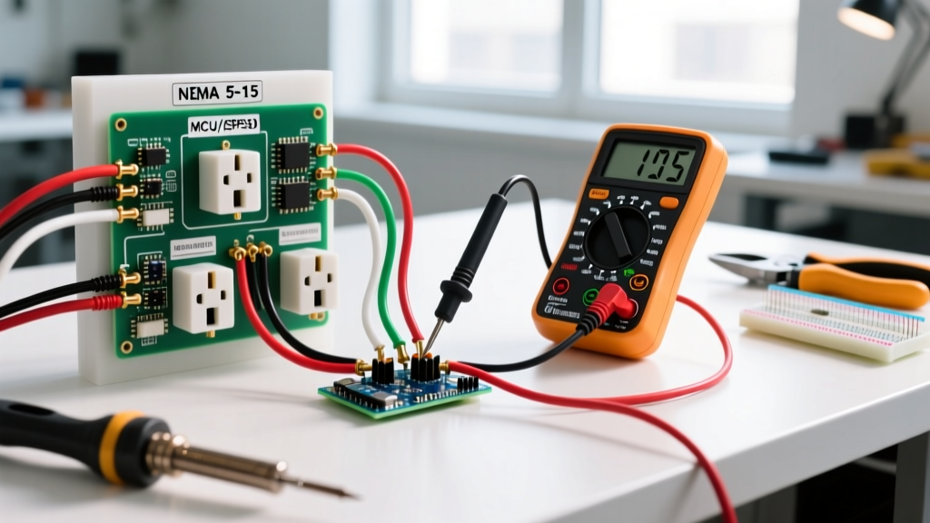
- True-RMS Digital Multimeter: The Fluke 117 (approx. $220) or Klein Tools MM400 (approx. $55) is mandatory for measuring exact AC voltage and detecting phantom voltages on open neutrals.
- Non-Contact Voltage Tester (NCVT): The Klein NCVT-3 ($35) detects both standard 120V and low-voltage 12V-48V AC, helping identify miswired doorbell transformers sharing a box.
- Receptacle Tester with GFCI Trip: The Gardner Bender GFI-3501 ($15) provides an immediate visual matrix for wiring faults and tests upstream GFCI trip circuits.
- Calibrated Torque Screwdriver: The Klein 602-8 or Milwaukee 48-22-0501. The 2017 and subsequent NEC updates strictly mandate torqueing terminations to manufacturer specifications, typically 14 in-lbs for standard 15A/20A devices.
Symptom-to-Cause Diagnostic Matrix
When a user reports an outlet issue, the physical symptoms provide the first clue. Use this matrix to narrow down the failure mode before removing the faceplate.
| Observed Symptom | Probable Root Cause | Primary Diagnostic Test | Repair Protocol |
|---|---|---|---|
| Dead outlet, no voltage | Tripped upstream GFCI, open hot, or backstabbed push-in failure | NCVT test, check upstream GFCI/AFCI breakers | Reset GFCI; re-terminate wires under screw terminals |
| Outlet works but feels warm/hot | High resistance connection, overloaded circuit, or undersized wire | Thermal imaging (FLIR), clamp-meter amperage check | Replace receptacle, verify wire gauge (12 AWG for 20A), reduce load |
| Plugs fall out easily | Worn internal brass contact tensioners (mechanical fatigue) | Physical plug retention test (UL standard pull-force) | Immediate receptacle replacement (no repair possible) |
| Reversed polarity (Hot/Neutral swapped) | Installer error at the device or upstream splice | Plug-in receptacle tester (red/yellow LED matrix) | Swap black (hot) and white (neutral) wires at brass/silver terminals |
| Audible buzzing or arcing sound | Loose terminal screw, internal contact arcing, or aluminum wire oxidation | Visual inspection for carbon scoring, torque check | Replace device; if aluminum, use CO/ALR rated device or AlumiConn pigtails |
Step-by-Step Troubleshooting: The 'Dead' Receptacle
The most common service call in residential electrical work is the dead outlet. Before cutting power, insert a plug-in receptacle tester. If all lights are dark, you have an open circuit. Follow this exact diagnostic sequence:
1. Verify the Upstream GFCI and Breaker
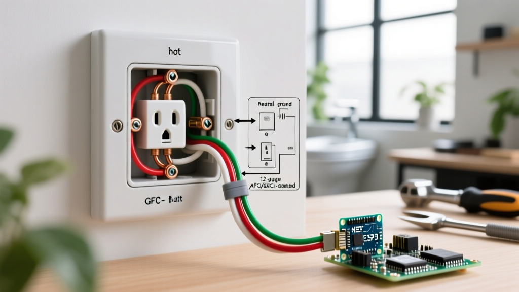
Modern NEC codes require Ground Fault Circuit Interrupter (GFCI) protection in kitchens, bathrooms, garages, exteriors, and unfinished basements. A single GFCI receptacle wired on the 'LOAD' terminals can protect up to four downstream standard receptacles. If a standard outlet in a bedroom shares a wall with a bathroom, it may be fed from the bathroom GFCI. Trip and reset all GFCI devices in the immediate vicinity. If the outlet remains dead, check the main panel for a tripped AFCI/GFCI breaker.
2. Isolate the Circuit and Open the Device
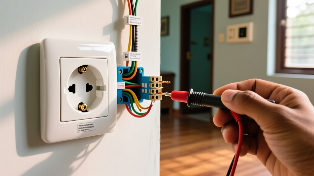
Turn off the breaker and verify zero voltage at the outlet using your True-RMS multimeter (set to V AC). Measure Hot-to-Neutral, Hot-to-Ground, and Neutral-to-Ground. All three should read 0.00V. Remove the faceplate and extract the receptacle from the box.
3. Inspect for 'Backstabbed' Connections
This is the most frequent culprit for dead outlets in homes built between 1980 and 2015. 'Backstabbing' involves pushing stripped 14 AWG or 12 AWG solid copper wire into spring-loaded holes on the back of the yoke. These internal brass springs fatigue over years of thermal expansion and contraction, eventually losing contact pressure. The Repair: Pull the wires out using a small flathead screwdriver in the release slot. Strip 3/4 inch of fresh insulation using wire strippers (e.g., Klein 11055). Form a J-hook with needle-nose pliers, loop it clockwise around the brass (hot) and silver (neutral) terminal screws, and tighten with a torque screwdriver set to 14 in-lbs. This ensures a gas-tight, high-pressure mechanical bond that will not degrade.
Addressing Thermal Failures and Melted Yokes
If an outlet exhibits brown scorch marks, a melted plastic yoke, or emits a burning odor, you are dealing with a high-resistance thermal failure. According to OSHA electrical safety guidelines, heat generation in a circuit is proportional to the square of the current multiplied by the resistance (P = I²R). A loose terminal screw creates micro-arcing and immense localized heat, even if the overall circuit breaker (which only monitors total amperage) does not trip.
CRITICAL WARNING: Never simply replace a scorched receptacle and re-terminate the same damaged wires. Heat alters the crystalline structure of copper, making it brittle and highly resistive. You must cut back the damaged wire to bright, clean copper. If this leaves insufficient wire length (less than 3 inches past the box edge), you must use a UL-listed wire nut or WAGO 221 lever-nut to pigtail a new extension.
Checking Wire Gauge and Breaker Sizing
Thermal damage often occurs when a 20-Amp breaker is mistakenly paired with 14 AWG wire (rated only for 15 Amps). The wire acts as a heating element before the breaker trips. Always verify the wire gauge. If you see white-jacketed NM-B cable (Romex), it contains 14 AWG wire and must be on a 15A breaker. Yellow-jacketed NM-B contains 12 AWG wire and can be used on 15A or 20A circuits. If the circuit is 20A, the replacement receptacle must be a 20A-rated device (identified by the T-slot neutral aperture) or a 15A duplex receptacle specifically listed for 20A pass-through.
Polarity, Grounding, and Code Compliance
A receptacle that functions but has reversed polarity (hot and neutral swapped) or an open ground presents a severe shock hazard. In a reversed polarity scenario, the internal switch of an appliance (like a lamp) breaks the neutral path, leaving the internal components energized at 120V even when turned off.
Diagnosing an Open Ground: If your receptacle tester indicates an open ground, do not simply install a GFCI receptacle and call it a day. While the NEC allows a GFCI to replace an ungrounded receptacle as a safety upgrade (provided it is labeled 'No Equipment Ground' and 'GFCI Protected'), this does not provide a true equipment grounding path for sensitive electronics like PCs or audio equipment. The only true repair for an open ground is to run a new equipment grounding conductor (EGC) back to the panel or to a verified grounding electrode system.
Special Case: Aluminum Branch Wiring
Homes built in the late 1960s and early 1970s often feature solid aluminum branch wiring. Aluminum oxidizes rapidly when exposed to air, creating a highly resistive aluminum oxide layer that causes overheating at copper-only receptacle terminals. Never connect aluminum wire directly to a standard brass/silver terminal. To repair an outlet on an aluminum circuit, you must either install a receptacle specifically stamped 'CO/ALR' (Copper/Aluminum Revised) or, preferably, use AlumiConn aluminum-to-copper lug connectors to pigtail a short copper lead to a standard receptacle.
Frequently Asked Questions (FAQ)
Can I just wrap loose wires in electrical tape instead of replacing the outlet?
No. Electrical tape provides zero mechanical retention and degrades under thermal cycling. If the internal brass contacts of the receptacle are loose (plugs fall out), the device is mechanically failed and must be replaced. Tape is only permitted as a secondary wrap over properly installed wire nuts in specific junction box scenarios, not for terminal connections.
Why does my outlet buzz when I plug in a high-draw appliance like a vacuum?
A buzzing sound indicates micro-arcing. This happens when the internal contact blades of the receptacle no longer grip the plug prongs tightly, or when the terminal screws on the side of the yoke are loose. The arcing generates plasma and extreme heat, which is a direct precursor to an electrical fire. Turn off the breaker immediately and replace the receptacle.
Is it safe to repair an outlet that has painted-over slots?
Paint inside the slot acts as an insulator, preventing the plug prongs from making full metallic contact with the internal brass wipers. This increases resistance and causes localized heating. While you can try to scrape the paint out with a small file, the solvent in the paint often degrades the internal plastic. Replacement is the only code-compliant and safe repair.