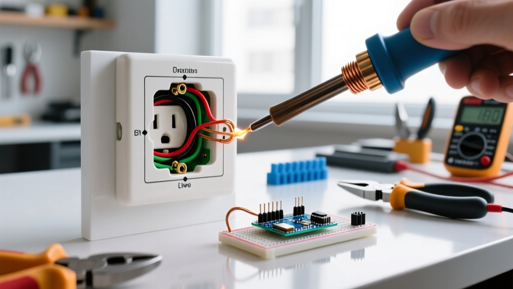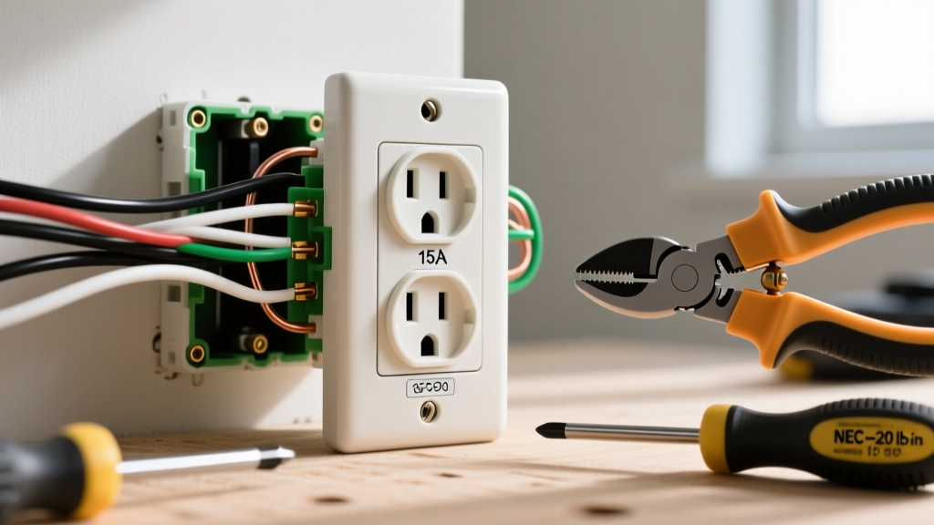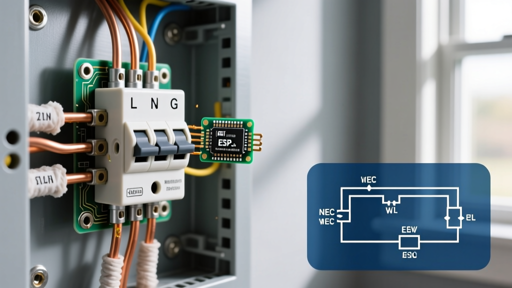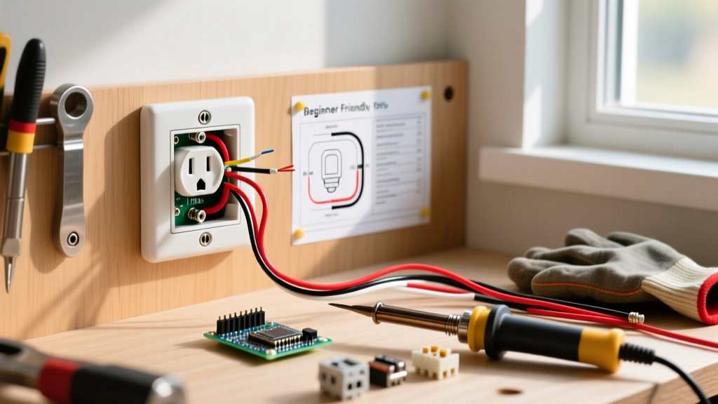

Why Upgrade Your Outdoor Receptacle? The Hidden Risks of Aging Hardware
If you are installing an outdoor electrical outlet to replace an aging, cracked, or non-compliant receptacle, you are addressing one of the most critical safety vulnerabilities on a property's exterior. Older outdoor outlets often suffer from degraded UV-exposed plastics, corroded internal contacts, and missing ground-fault protection. When upgrading, the goal is not merely to restore power, but to engineer a weatherproof, code-compliant node that can withstand extreme thermal cycling, driving rain, and UV radiation for the next 15 to 20 years.
Common Failure Modes in Older Outdoor Outlets
- Galvanic Corrosion: Standard indoor receptacles placed outside will develop green/white oxidation on the brass terminal screws within 6 to 12 months, leading to high-resistance connections and potential arc faults.
- UV Degradation: Standard nylon faceplates become brittle and shatter upon impact after prolonged sun exposure, exposing live 120V terminals to the elements.
- Flat Cover Violations: Using flat, flip-lid metal covers while a cord is plugged in violates modern electrical codes, as it forces the cover open, exposing the receptacle to direct rainfall.
Current NEC Standards for Outdoor Receptacles
When planning your upgrade, adherence to the National Electrical Code (NEC) is non-negotiable. The National Fire Protection Association (NFPA) mandates specific hardware for damp and wet locations. Under NEC Article 406.9(B)(1), all 15A and 20A, 125V outdoor receptacles must be protected by an extra-duty weatherproof cover (often called a bubble or in-use cover) that remains weatherproof even when a cord is plugged in. Furthermore, NEC Article 210.8(A)(3) requires Ground-Fault Circuit Interrupter (GFCI) protection for all outdoor outlets.
Expert Note: Do not rely on a GFCI breaker in the main panel alone if the outdoor wiring run exceeds 50 feet. Long wire runs accumulate capacitive leakage current, which can cause nuisance tripping at the breaker. Installing a local WR (Weather-Resistant) GFCI receptacle at the point of use is the superior, code-compliant upgrade path.
Materials & Cost Breakdown for a Professional Upgrade
Skip the builder-grade hardware. The following table outlines the professional-tier components required for a durable exterior installation in 2026.
| Component | Recommended Model / Spec | Avg. Cost | Why It Matters |
|---|---|---|---|
| Receptacle | Leviton GFNT2-W (20A WR GFCI) | $28 - $32 | Features UV-stabilized thermoplastics and nickel-plated brass contacts to resist corrosion. |
| Weatherproof Cover | Taymac ML550B Extra-Duty In-Use | $14 - $18 | Provides 2.75 inches of depth, accommodating bulky transformer plugs while sealing out rain. |
| Conduit Connectors | Arlington BE1 Non-Metallic Push-In | $3 - $5 | Creates a watertight seal at the hub entries without requiring locknut threading. |
| Sealant | GE Silicone II (100% Silicone) | $8 - $10 | Remains flexible across -40°F to 120°F. Acrylic caulks will crack and fail in exterior thermal swings. |
Step-by-Step Installation & Upgrade Guide
Follow this precise workflow to ensure your new outdoor electrical outlet is safe, sealed, and compliant.
Step 1: Power Verification and Extraction
Shut off the circuit breaker and verify the absence of voltage using a non-contact voltage tester (e.g., Klein NCVT-3). Test both the top and bottom receptacles. Remove the old cover plate, unscrew the mounting strap, and carefully pull the old receptacle out of the box. Do not touch the bare wires until you have verified zero voltage.
Step 2: Box Preparation and Hub Sealing
If you are replacing a rusted cast-aluminum box with a modern PVC weatherproof box, ensure the mounting surface is flat. Feed your UF-B cable or THWN wires through the conduit into the box. Apply a generous bead of duct seal or 100% silicone around the conduit hub entries where they meet the box. This prevents capillary action from drawing moisture into the enclosure.
Step 3: Wiring the WR GFCI Receptacle
Strip exactly 3/4 inch of insulation from your 12 AWG or 14 AWG wires. CRITICAL: Never use the backstab push-in holes on a GFCI receptacle. Thermal expansion and contraction outdoors will loosen the internal grips, leading to arcing. Instead, use the side-clamp screw terminals:
- Connect the bare copper ground wire to the green grounding screw. Torque to 14 in-lbs.
- Connect the white neutral wire to the silver LINE terminal screw.
- Connect the black hot wire to the brass LINE terminal screw.
- Wrap electrical tape around the sides of the GFCI body to cover the exposed terminal screws. This prevents accidental shorting against a metal box or moisture condensation.
Step 4: Mounting and the 'Weep Hole' Sealing Technique
Carefully fold the wires into the back of the box using a sweeping loop—never jam them in, as this can pinch the insulation. Mount the receptacle to the box. Next, attach your extra-duty bubble cover. When applying your GE Silicone II sealant around the perimeter of the cover flange against the siding or brick, leave the bottom 1/2 inch of the flange uncaulked. This creates a vital 'weep hole.' If microscopic condensation forms inside the cover due to humidity shifts, gravity will pull the water down and allow it to drain out the bottom rather than pooling inside the electrical box.
Troubleshooting: Nuisance Tripping & Moisture Ingress
Even with a flawless installation, outdoor environments present unique edge cases. If your newly installed outdoor electrical outlet trips immediately or intermittently, consider the following diagnostics:
- Condensation Bridging: If you used a standard indoor GFCI instead of a WR (Weather-Resistant) model, internal condensation can bridge the sensing coil circuit. Fix: Replace with a WR-rated model featuring conformal-coated internal electronics.
- Downstream Leakage: If you wired the 'LOAD' terminals to feed another outdoor light or receptacle, a fault anywhere on that downstream run will trip your main GFCI. Fix: Keep outdoor GFCIs dedicated to a single point of use whenever possible, or upgrade downstream nodes to their own local GFCI protection.
- Wire Strand Shorts: A single stray strand of copper from the hot wire touching the grounded metal box will cause an immediate trip. Fix: Trim wires cleanly, ensure no bare copper is exposed outside the terminal clamp, and apply electrical tape over the terminals.
Final Safety Verification
Once the silicone has cured (typically 24 hours for a full weatherproof seal), restore power at the breaker. Press the 'TEST' button on the GFCI receptacle; it should click and cut power. Press 'RESET' to restore. Plug in a heavy-load outdoor device (like a leaf blower or electric trimmer) to ensure the 20A pass-through contacts are seated firmly. For more on exterior electrical safety and ground-fault protection mechanics, consult the Consumer Product Safety Commission (CPSC) electrical safety guidelines.
By selecting UV-stabilized, weather-resistant components and employing the weep-hole sealing technique, your upgraded outdoor receptacle will provide safe, reliable power for years to come, completely insulated from the harshest environmental factors.