
Understanding Baseboard Electrical Outlet Configurations
When conducting residential or light-commercial electrical inspections, the baseboard electrical outlet presents a unique set of challenges unlike standard wall-mounted receptacles. These outlets are typically subjected to higher ambient temperatures, physical abrasion from vacuums and foot traffic, and complex daisy-chain wiring constraints. In 2026, with the rise of smart baseboard heaters drawing continuous standby current for Wi-Fi thermostats, verifying the integrity of these low-profile circuits is more critical than ever.
Before pulling out your multimeter, you must identify which of the two primary baseboard outlet configurations you are testing. Each requires a distinct inspection methodology and adheres to different sections of the National Electrical Code (NEC).
| Feature | Integrated Heater Receptacle (e.g., Cadet BSK1) | Surface Raceway Outlet (e.g., Wiremold 2800) |
|---|---|---|
| Mounting | Factory-integrated into the end-cap of a 240V/120V baseboard heater. | Surface-mounted metallic or PVC channel running along the floor-wall joint. |
| Primary Hazard | Thermal degradation of the thermoplastic yoke from heater proximity. | Physical crushing, wire pinch-points, and improper splice enclosures. |
| Average Replacement Cost | $35 - $45 (OEM receptacle kit) | $80 - $120 (10-foot raceway run with fittings) |
| NEC Focus Area | Article 424 (Fixed Electric Space Heating Equipment) | Article 344 (Surface Metal Raceways) & Article 362 (Surface PVC) |
Visual Inspection Protocol: Spotting Heat and Strain
A rigorous visual inspection of a baseboard electrical outlet must precede any live electrical testing. Because these outlets sit at floor level, they are prime targets for physical damage and environmental degradation.
1. Thermoplastic and Yoke Degradation
Integrated heater receptacles are exposed to convective heat loops. Over time, standard nylon or polycarbonate faceplates can become brittle, yellow, or warp. Inspect the terminal yoke for micro-fractures. If the outlet face feels excessively hot to the touch when the heater is off, or if the plastic shows a brownish heat-tint, the internal brass contacts have likely lost their spring tension, leading to high-resistance arcing.
2. Cord Strain and Clearance Violations
Furniture placement often forces users to bend plugs at severe angles against baseboard outlets. Check for splayed prongs, cracked plug housings, and exposed copper stranding at the cord strain relief. Furthermore, verify that no combustible materials (like heavy drapery or wood trim) are resting directly against the outlet face, which violates basic clearance principles outlined by the National Fire Protection Association (NFPA).
3. Raceway Enclosure Integrity
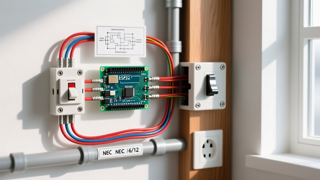
For Wiremold or surface raceway baseboard outlets, inspect the channel covers. Are they fully seated? A common DIY failure is forcing a cover over a 12 AWG wire splice that was not properly tucked into an approved junction box within the raceway, creating a severe pinch-point that compromises the wire insulation.
Step-by-Step Multimeter Testing Procedure
Once visual clearance is granted, proceed to live electrical testing. You will need a True-RMS digital multimeter (such as the Fluke 117 or Klein MM400) and a non-contact voltage tester. Ensure you are wearing appropriate PPE as recommended by OSHA Electrical Safety Standards.
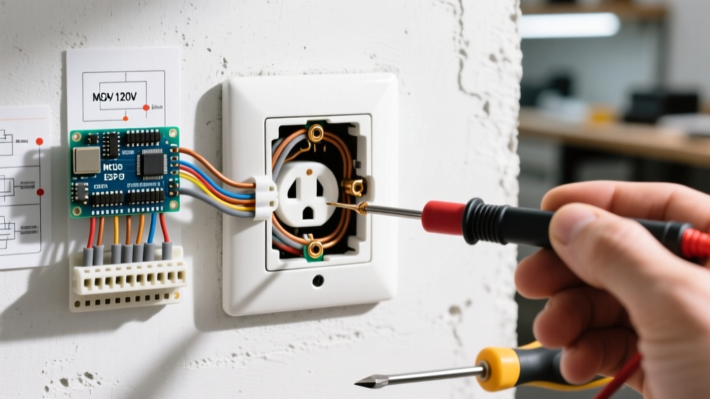
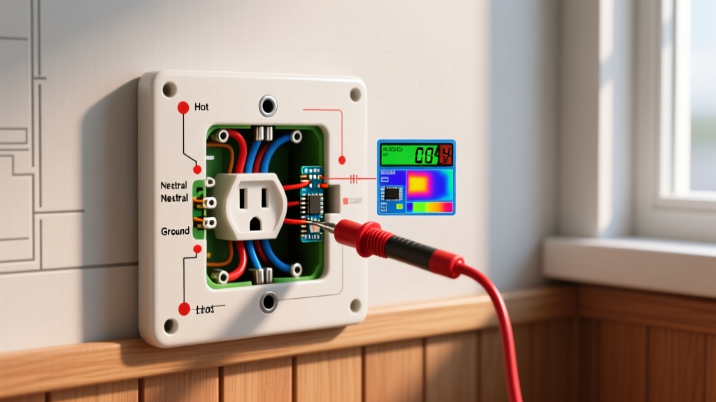
- Verify Voltage Presence: Set your multimeter to AC Voltage (V~). Insert the probes into the hot (short slot) and neutral (long slot). You should read between 114V and 126V (for standard 120V circuits). A reading below 110V under no-load conditions indicates a high-resistance connection upstream, often caused by a loose backstabbed wire in a preceding daisy-chained baseboard outlet.
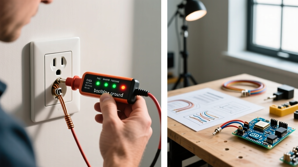
- Test Ground Integrity: Move the black probe to the neutral slot and the red probe to the ground pin (U-shape). You should read 0V. Next, measure Hot-to-Ground. This should match your Hot-to-Neutral reading within 1-2 volts. A significant discrepancy indicates a compromised equipment grounding conductor (EGC), which is highly dangerous in metallic surface raceways.
- Check for Reverse Polarity: Measure Neutral-to-Ground. This must read 0V to 0.5V. If you read 120V, the hot and neutral wires have been reversed at the outlet or the upstream splice—a frequent error in retrofitted baseboard raceway installations.
- Load Testing (Voltage Drop): Plug in a known 1500W resistive load (like a hair dryer or heat gun) into the baseboard electrical outlet. Monitor the voltage. A drop of more than 5% (below 114V) under load confirms undersized wiring, excessive circuit length, or corroded terminal screws.
Expert Note on Torque: If you open the outlet to inspect terminations, remember that 14 AWG and 12 AWG copper wires on standard 15A/20A receptacles require a tightening torque of 12 to 14 inch-pounds. Hand-tightening often leads to thermal expansion/contraction cycles that loosen the screw over time, a primary cause of baseboard outlet fires.
Thermal Imaging for Hidden Degradation
Visual and multimeter tests cannot always detect early-stage high-resistance faults inside the outlet body. Using a thermal imaging camera (like the FLIR E8-XT) is the gold standard for inspecting baseboard electrical outlets under load.
According to FLIR Electrical Inspection Guidelines, you should scan the outlet face while the circuit is under at least 40% of its rated load. Look for the Delta T (temperature differential) between the outlet face and the ambient wall temperature.
- Delta T < 5°C (9°F): Normal operating temperature. No action required.
- Delta T 5°C to 10°C (9°F to 18°F): Marginal. Schedule a follow-up inspection in 6 months. Check for loose terminal screws.
- Delta T > 10°C (18°F): Critical failure imminent. The internal brass contacts are arcing or the wire terminations are loose. De-energize the circuit and replace the receptacle immediately.
Troubleshooting Matrix: Common Baseboard Outlet Failures
When an inspection reveals an anomaly, use this matrix to diagnose the root cause and determine the correct remediation strategy.
| Symptom / Finding | Probable Root Cause | Corrective Action |
|---|---|---|
| Plugs fall out easily; loose physical grip. | Worn internal brass contact wipers due to heat cycling or physical abuse. | Replace the receptacle. Do not attempt to bend the prongs of the plug to compensate. |
| GFCI trips immediately when heater turns on. | Heater element degradation causing ground fault leakage, or shared neutral with another circuit. | Megohmmeter test the heater element. Verify GFCI is not protecting a non-compliant shared neutral. |
| Buzzing sound from surface raceway outlet. | Loose wire splice vibrating under AC magnetic fields, or backstabbed connection failing. | Open raceway, remove backstabbed connections, and terminate using screw terminals with proper torque. |
| Outlet face is physically melted or deformed. | Sustained overloading (e.g., plugging a 15A space heater into a 15A baseboard outlet already sharing a loaded circuit). | Replace outlet, inspect wire insulation for 6 inches upstream/downstream, and redistribute circuit loads. |
NEC Compliance and Clearance Rules
Inspectors must cross-reference baseboard electrical outlet placements with NEC Article 210.52, which mandates that no point along a floor line in any wall space is more than 6 feet from a receptacle. However, baseboard heaters complicate this rule.
You cannot count a receptacle integrated into a 240V baseboard heater toward the 120V general lighting and appliance branch circuit requirements unless it is an isolated, dedicated 120V receptacle kit wired to a separate 120V breaker. Furthermore, NEC Article 424 strictly prohibits placing combustible materials against the heater, which inherently restricts how furniture can be placed near integrated outlets. When inspecting older homes, it is common to find baseboard outlets that were improperly wired in series with the 240V heating elements—a lethal code violation that must be red-tagged immediately.
Final Inspection Sign-Off
A thorough inspection of a baseboard electrical outlet requires moving beyond simple plug-in testers. By combining visual assessments for thermal and physical damage, precise True-RMS multimeter voltage drop testing, and thermal imaging under load, you can accurately predict and prevent catastrophic failures. Always document your Delta T readings and torque verification in your final inspection report to ensure long-term safety and code compliance.