
Essential Tools and Safety Protocols for Outlet Wiring
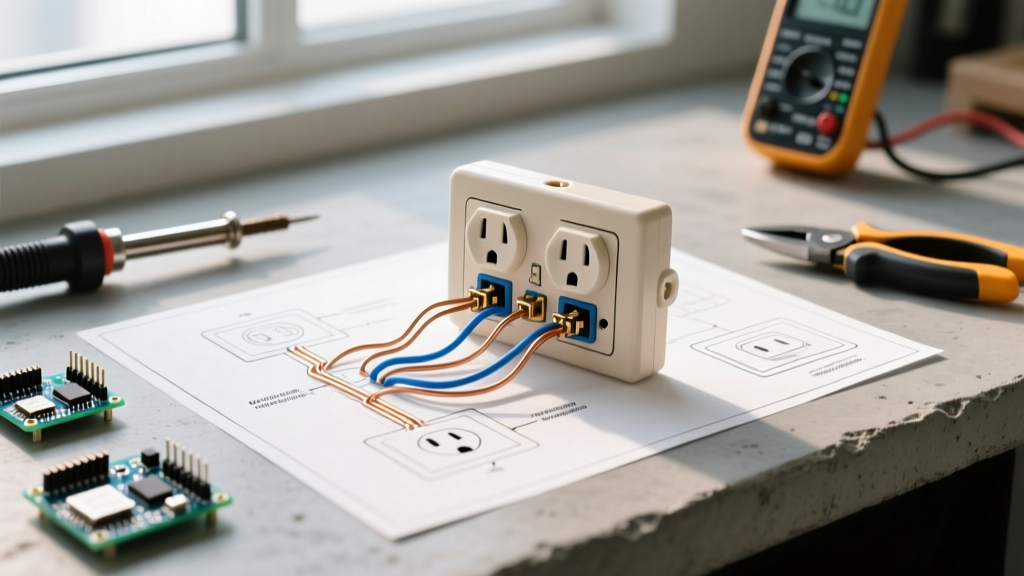
Connecting an electrical outlet is a foundational skill for any DIYer or apprentice electrician, but the modern electrical landscape demands more than just twisting wires together. With the widespread adoption of the 2023 and upcoming 2026 National Electrical Code (NEC) updates, the focus has shifted heavily toward arc-fault protection, precise torque specifications, and rigorous box-fill calculations. Before tackling any of the common wiring scenarios below, ensure the circuit is de-energized and verified with a non-contact voltage tester and a digital multimeter like the Fluke 117 ($250).
For professional-grade results, abandon generic hardware store tools. Invest in a dedicated wire stripper like the Klein Tools 11055 ($28) to avoid nicking copper conductors, which creates weak points that can snap under terminal pressure. Furthermore, NEC 110.14(D) now strictly mandates that terminals be tightened to the manufacturer's specified torque. A calibrated torque screwdriver, such as the Wiha 60060 ($120), is no longer optional for compliant, fire-safe installations. According to the National Fire Protection Association (NFPA 70), loose connections are a leading cause of residential electrical fires due to high-resistance arcing.
Scenario 1: Standard 15A and 20A Duplex Receptacles
The most frequent task is connecting an electrical outlet for standard household use. The critical first step is matching the receptacle rating to the breaker and wire gauge. A 15-amp circuit uses 14 AWG copper and requires a 15A receptacle (e.g., Leviton 5262-W). A 20-amp circuit uses 12 AWG copper and requires a 20A receptacle, identifiable by its T-shaped neutral slot.
End-of-Run vs. Middle-of-Run
- End-of-Run: Only one cable enters the box. You will connect the single black (hot) wire to the brass screw, the single white (neutral) wire to the silver screw, and the bare/green ground to the green screw.
- Middle-of-Run: Two cables enter the box (one feeding in, one feeding out). You must connect both black wires to the brass terminals and both white wires to the silver terminals. If your receptacle only has one screw per side, you must create a 'pigtail' using a short 6-inch piece of matching wire and a wire nut or Wago 221 lever connector.
Pro-Tip: Always use the side-wiring (screw) terminals or the rear 'clam-plate' back-wiring feature found on commercial-grade receptacles. Never use the push-in 'backstab' holes. Backstab connections rely on a small spring-metal wedge that loses tension over years of thermal expansion and contraction, leading to intermittent power loss and internal arcing.
Scenario 2: GFCI Protection in Wet Areas
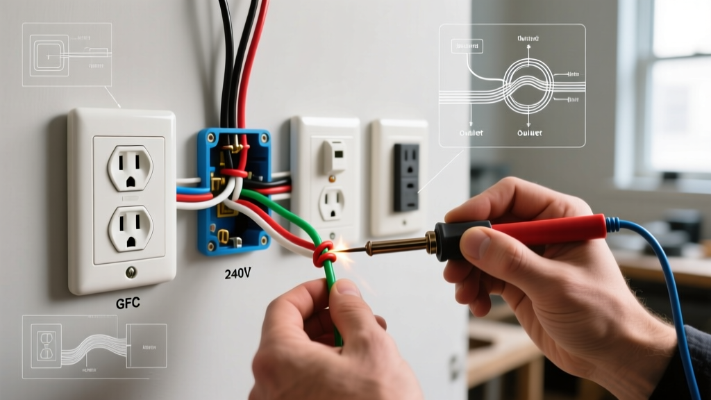
The U.S. Consumer Product Safety Commission (CPSC) strongly mandates Ground Fault Circuit Interrupter (GFCI) protection in kitchens, bathrooms, garages, and outdoor areas to prevent lethal shock hazards. When connecting an electrical outlet with GFCI protection, understanding the 'Line' vs. 'Load' distinction is where most DIYers fail.
Line vs. Load Wiring
A GFCI receptacle like the Leviton GFNT1-W ($22) has two sets of terminals: LINE and LOAD.
- LINE: This is where the incoming power from the breaker panel connects. If you only need to protect this single outlet, you only use the LINE terminals and cap off the LOAD terminals with electrical tape.
- LOAD: These terminals feed power downstream to other standard outlets, extending GFCI protection to them. If you wire incoming power to the LOAD terminals by mistake, the GFCI will not reset and will offer zero shock protection.
When pigtailing neutrals for a GFCI, ensure the equipment ground is connected first, followed by the neutrals, and finally the hots. This sequence prevents accidental short circuits if a tool slips during installation.
Scenario 3: Switched (Half-Hot) Receptacles
A switched outlet—often found in living rooms where one half of the duplex is controlled by a wall switch for a lamp, while the other half remains always-on—requires a specific physical modification to the receptacle.
Breaking the Brass Fin
To isolate the top and bottom receptacles, you must break the small brass connecting fin on the hot (brass) side of the outlet using needle-nose pliers. Do not break the silver fin on the neutral side. Breaking the neutral fin will create an open neutral on the downstream circuit if wired in a multi-wire branch circuit (MWBC), which can cause devastating overvoltage damage to connected electronics.
Wiring the Switch: You will need a 3-wire cable (e.g., 12/3 NM-B) running from the switch to the outlet. The black wire carries constant hot to the bottom brass screw. The red wire carries the switched hot from the wall switch to the top brass screw. The white neutral connects to the silver screw, and the ground to the green screw.
Scenario 4: 240V NEMA 14-50 for EV Chargers and Ranges
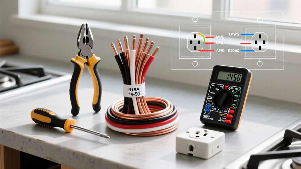
With the surge in home electric vehicle (EV) charging, connecting an electrical outlet for a NEMA 14-50 receptacle has become a highly requested scenario. This is a 240-volt, 50-amp circuit requiring heavy-gauge wire and strict adherence to torque specifications.
- Wire Gauge: 6 AWG copper (THHN in conduit or 6/3 NM-B Romex, though many local inspectors now require THHN in conduit for 50A EV circuits due to sustained continuous load heat dissipation).
- Breaker: 50-Amp double-pole breaker.
- Terminals: Two Hots (X and Y, usually black and red), one Neutral (W, white), and one Ground (G, green/bare).
Torque Warning: The terminal screws on a 50A receptacle are massive and require significant force. Manufacturer specifications typically demand 45 in-lbs (approx. 5.0 Nm) of torque. Hand-tightening is insufficient and will result in thermal melting of the receptacle face during a 40-amp continuous EV charging session.
Wiring Matrix and Torque Specifications
| Scenario | Receptacle Type | Wire Gauge (Copper) | Breaker Size | Typical Torque Spec |
|---|---|---|---|---|
| Standard Lighting/General | 15A Duplex (NEMA 5-15R) | 14 AWG | 15A | 12 in-lbs (1.4 Nm) |
| Kitchen/Bathroom Appliances | 20A Duplex (NEMA 5-20R) | 12 AWG | 20A | 14 in-lbs (1.6 Nm) |
| Wet Area Shock Protection | 20A GFCI | 12 AWG | 20A | 14 in-lbs (1.6 Nm) |
| EV Charger / Electric Range | 50A (NEMA 14-50R) | 6 AWG | 50A | 45 in-lbs (5.0 Nm) |
Critical Failure Modes and Troubleshooting
Even when following the steps for connecting an electrical outlet, subtle errors can lead to catastrophic failures. Here are the most common edge cases and how to avoid them:
1. The Shared Neutral Trip (GFCI/AFCI)
If you are replacing an older outlet in a home wired with a Multi-Wire Branch Circuit (two hots sharing one neutral), connecting a standard GFCI receptacle will result in immediate nuisance tripping. GFCIs monitor the exact current balance between hot and neutral. A shared neutral returns current from a different hot wire, causing an imbalance that the GFCI interprets as a ground fault. Solution: Use a 2-pole AFCI/GFCI breaker in the panel instead of a point-of-use GFCI receptacle for MWBCs.
2. Box Fill Violations (NEC 314.16)
Cramming four 12 AWG cables, three wire nuts, and a GFCI receptacle into a standard 18-cubic-inch plastic box violates NEC box fill rules. The heat generated by the GFCI's internal electronics cannot dissipate, leading to premature failure. Always calculate box fill: each 12 AWG wire counts as 2.25 cubic inches. When in doubt, upgrade to a 22-cubic-inch 'deep' box or use a masonry ring extender.
3. Reversed Hot and Neutral (Polarity Issue)
If the black wire is placed on the silver screw and the white wire on the brass screw, the outlet will still power a lamp. However, the internal switch of the appliance will now break the neutral path instead of the hot path. This leaves the appliance's internal components energized at 120V even when turned off, creating a severe shock hazard if a user attempts to repair or clean the device. Always verify correct polarity with a $15 receptacle tester before energizing the circuit.
Expert Insight: When stripping insulation for side-wiring, aim for exactly 3/4 of an inch. If you strip too little, the insulation binds under the screw head washer, preventing a tight mechanical and electrical connection. If you strip too much, you leave exposed copper outside the terminal, creating a short-circuit hazard if the wire shifts inside the box.
By understanding the distinct requirements of each scenario—from the delicate fin-breaking of a switched outlet to the heavy-duty torque demands of a NEMA 14-50—you ensure your electrical system is not only functional but fundamentally safe and compliant with modern codes.