
Understanding the Type F Electrical Outlet (Schuko)
The type f electrical outlet, universally recognized as the Schuko (from the German Schutzkontakt, meaning 'protective contact'), is the dominant receptacle standard across Continental Europe, Russia, and parts of Asia. Defined by the CEE 7/3 standard for the socket and CEE 7/4 for the plug, this robust 16A, 230V system is engineered for high safety and durability. Unlike the North American NEMA 5-15, the Type F relies on dual side-grounding clips rather than a dedicated third pin, ensuring that earth contact is made before the live pins engage when inserting a plug.
As of 2026, with the increasing power demands of modern home appliances and the integration of smart home energy monitors, properly wiring and retrofitting Type F receptacles requires strict adherence to IEC 60884-1 standards and local electrical codes. Below, we break down the most common wiring scenarios, from new masonry installations to complex legacy retrofits.
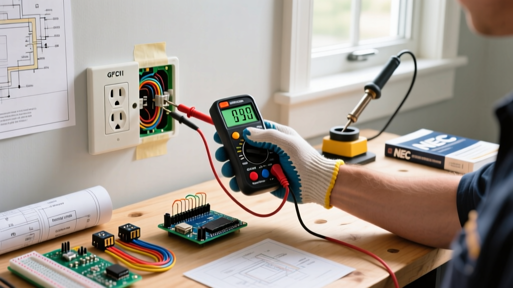
⚠️ CRITICAL SAFETY WARNING: Working with 230V/16A circuits carries a severe risk of arc flash and electrocution. Always isolate the circuit at the main distribution board (DB) and verify zero voltage using a CAT III or CAT IV multimeter before touching any terminals. If you are unsure about local earthing regulations, consult a certified electrician.Technical Specifications & Anatomy
Before tackling any wiring scenario, it is vital to understand the physical and electrical parameters of the Type F system. The receptacle features two 4.8mm round pins spaced exactly 19mm apart, surrounded by a 44mm circular recess that houses the grounding clips.
| Feature | Type F (Schuko) | Type E (French/Belgian) | Type C (Europlug Receptacle) |
|---|---|---|---|
| Socket Standard | CEE 7/3 | CEE 7/5 | N/A (Unearthed) |
| Grounding Mechanism | Dual side metal clips | Single male earth pin | None |
| Max Current Rating | 16A | 16A | 2.5A (Plug limit) |
| Standard Pin Spacing | 19mm | 19mm | 19mm |
Scenario 1: New Flush-Mounted Installation in Masonry
The most common scenario for DIYers and professionals in regions like Germany, Spain, and Eastern Europe is installing a new Type F receptacle into a standard flush-mounted box (Unterputzdose). Standard European masonry boxes measure 68mm in diameter.
Step-by-Step Wiring Procedure
- Cable Selection: For standard 16A socket circuits, use NYM-J 3x1.5mm² solid copper cable. If the circuit is dedicated to high-continuous-draw appliances (like a 2026-era portable EV charger or a 3kW space heater), upgrade to NYM-J 3x2.5mm² to prevent thermal degradation over time.
- Stripping the Sheath: Strip the outer grey PVC jacket back approximately 120mm from the entry point of the flush box. Strip the individual conductor insulation to exactly 12mm. Exposed copper beyond the terminal block is a major shock hazard.
- Terminal Connections:
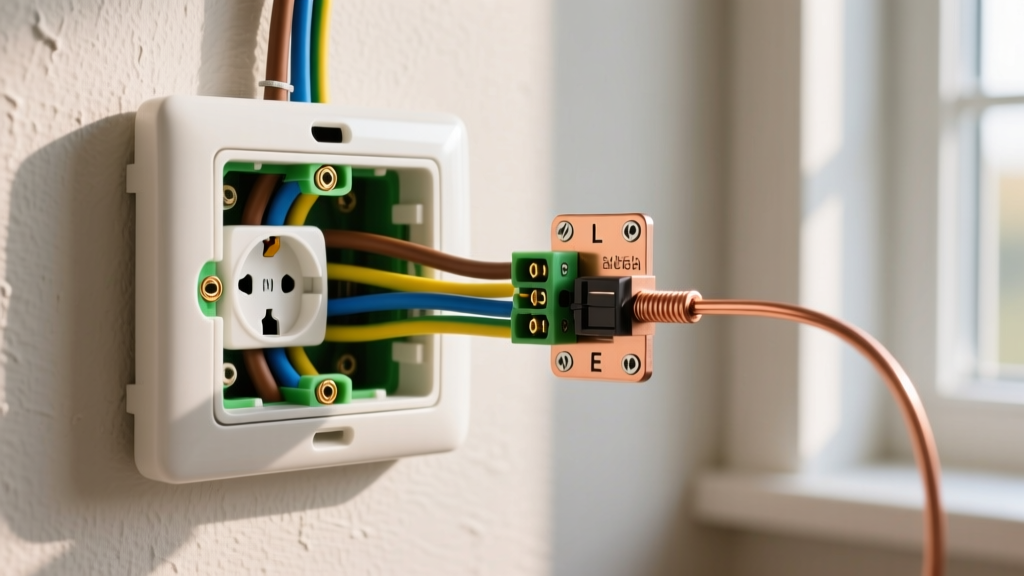
- Phase (L1): Connect the Brown wire to the terminal marked 'L' (usually on the right side when facing the socket).
- Neutral (N): Connect the Blue wire to the terminal marked 'N' (usually on the left).
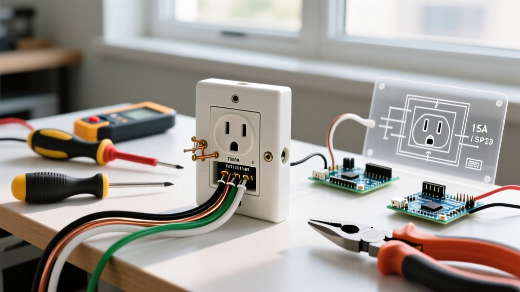
- Protective Earth (PE): Connect the Green/Yellow wire to the central or top earth terminal. This terminal is physically bridged to the two side grounding clips inside the Schuko recess.
- Torque Application: This is where most amateurs fail. Use a calibrated torque screwdriver set to 0.8 Nm (check the manufacturer's stamp on the back of the socket; Legrand and Schneider Electric typically specify 0.5 to 0.8 Nm). Under-tightening causes arcing; over-tightening crushes the solid copper core, leading to cold flow deformation and eventual loose connections.
Scenario 2: Retrofitting Pre-1980s Ungrounded Circuits
In many older European buildings, you will encounter a dangerous legacy wiring method known in Germany as Klassische Nullung (classical neutral grounding). In this obsolete setup, the protective earth terminal on the socket was bridged directly to the neutral terminal using a small jumper wire, relying on the neutral wire to act as both the return path and the earth.
Expert Insight: If the neutral wire in a Klassische Nullung circuit were to break upstream, the metal casing of any plugged-in appliance would instantly become energized at 230V. This practice was banned decades ago but remains hidden behind millions of old Type F faceplates.
The Remediation Strategy
When you open an old Type F socket and find a jumper wire between the N and PE terminals, remove it immediately. You have two code-compliant paths forward:
- Path A (Ideal): Pull a new 3-core (NYM-J 3x1.5mm²) cable from the distribution board to provide a dedicated Protective Earth (PE) line back to the main earth bar.
- Path B (Compromise): If structural constraints make rewiring impossible, you must leave the PE terminal on the socket completely disconnected and isolated. To provide shock protection, you must replace the standard MCB breaker at the panel with a 30mA RCBO (Residual Current Breaker with Overcurrent protection). Note: While an RCBO protects against earth leakage, the appliance chassis may still float at a lower voltage potential until a fault occurs. Always label the socket 'No Earth Present'.
Scenario 3: Integrating Behind-the-Socket Smart Relays
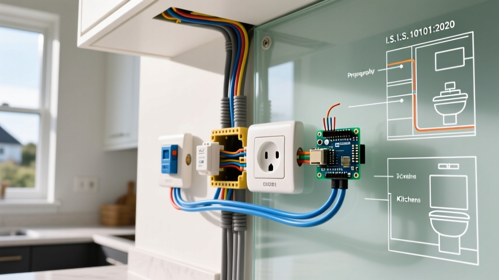
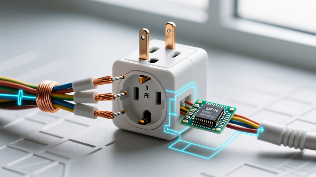
As of 2026, integrating Matter-over-Thread smart home devices is standard practice. Hardwiring a smart relay (like the Shelly Plus 1PM or Aqara Smart Plug Module) directly behind a Type F socket allows for seamless energy monitoring and automation without relying on bulky smart plugs.
The Depth Problem
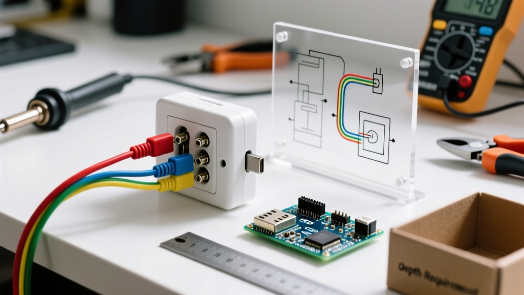
A standard smart relay measures roughly 39mm x 36mm x 16mm. A standard 47mm deep flush box leaves almost zero room for the stiff 1.5mm² solid copper wires to bend without pushing the relay against the back of the socket, causing severe mechanical stress on the terminals.
The Solution: Always use a 63mm deep flush box (often called a 'deep box' or tiefe Dose) when planning a smart socket installation.
Wiring the Relay
- Route the Phase (Brown) wire into the relay's 'L' input terminal.
- Run a short 1.5mm² pigtail wire from the relay's 'O' (Output) terminal to the 'L' terminal on the Type F socket.
- Wire the Neutral (Blue) directly to the socket's 'N' terminal, and use a Wago 221-3 connector to branch a pigtail to the relay's 'N' input (the relay needs neutral to power its internal Wi-Fi/Thread radio).
- Wire the Earth (Green/Yellow) directly to the socket's 'PE' terminal. Never route the earth wire through a smart relay.
Common Failure Modes & Troubleshooting
Even perfectly installed Type F outlets can experience degradation. Here is how to diagnose the most common field failures:
1. Thermal Runaway at 16A Continuous Load
Symptom: The faceplate feels warm to the touch, and there is a faint smell of ozone or melting PVC after running a portable EV charger or heavy heater for 3+ hours.
Cause: Standard 1.5mm² wire and standard socket terminals are rated for 16A, but continuous loads (defined by the IET as running for 3 hours or more) generate cumulative heat that standard terminals struggle to dissipate.
Fix: For dedicated high-draw circuits, upgrade the wiring to 2.5mm² and use heavy-duty industrial-grade Type F receptacles (e.g., Schneider Electric Odace or Legrand Mosaic) featuring larger, silver-plated terminal blocks.
2. Loose Grounding Clips (Arcing)
Symptom: Plugs feel 'loose' or wobbly when inserted. You may hear a faint buzzing sound when a high-draw appliance is active.
Cause: The side metal grounding clips on cheap or aged Type F sockets lose their spring tension over time. This increases contact resistance, leading to micro-arcing and eventual melting of the plug's earth contacts.
Fix: Replace the receptacle immediately. Do not attempt to bend the clips back into place, as the metal fatigue will cause them to snap or lose tension again within weeks.
Frequently Asked Questions (FAQ)
Can I plug a Type E (French) plug into a Type F socket?
Historically, no. Type E plugs have a male earth pin that would physically collide with the flat face of a pure Type F socket. However, since the late 1990s, the CEE 7/7 hybrid plug was introduced, featuring both side earth contacts (for Type F) and a female hole for the male earth pin (for Type E). If your appliance has a modern CEE 7/7 plug, it will work perfectly and safely in a Type F outlet.
Is it legal to install a Type F socket in the UK?
No. According to the UK's IET Wiring Regulations (BS 7671), standard household receptacles must be the BS 1363 (Type G) standard, which incorporates fused plugs and specific shutter mechanisms to prevent child tampering. Type F sockets lack these shutters and are not approved for general domestic use in the UK, though they may be found in specialized environments like server racks or specific industrial setups.
Why does my Type F socket have four terminals on the back?
High-quality Type F receptacles often feature 'loop-through' terminals. This means there are two L terminals, two N terminals, and two PE terminals. This allows you to daisy-chain the circuit to the next socket in the series without having to crimp multiple wires into a single terminal block or use external junction boxes, ensuring a cleaner, safer, and more reliable connection.
Further Reading & Authoritative Standards
For deeper technical specifications and regional compliance codes, consult the following authoritative resources:
- World Standards: Type F Plug and Socket Specifications - Comprehensive breakdown of the CEE 7/3 and CEE 7/4 physical dimensions and global usage maps.
- International Electrotechnical Commission (IEC) - The governing body for the IEC 60884-1 standard, which dictates the safety, testing, and dimensional requirements for household plugs and socket-outlets globally.
- The Institution of Engineering and Technology (IET) - Publishers of the BS 7671 Wiring Regulations, offering vital guidance on continuous load calculations and earthing arrangements for modern electrical installations.