
Mastering Blueprint Symbols for Electrical Rough-Ins
Before you purchase a single spool of Romex or a pallet of junction boxes, you must accurately interpret the architectural and electrical blueprints. Misreading a symbol for electrical outlet can lead to catastrophic material shortages, failed inspections, and costly change orders. In modern construction and high-end residential remodeling, the electrical plan is the definitive roadmap for your Bill of Materials (BOM). This guide decodes standard and specialized outlet symbols, translating them into actionable material lists, precise box-fill calculations, and the exact tools required for a flawless rough-in.
The Anatomy of the Standard Outlet Symbol
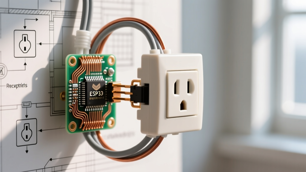
At its core, the universal symbol for electrical outlet on North American blueprints is a circle intersected by two parallel vertical lines, resembling a stylized wall receptacle. However, architectural drafters and electrical engineers use modifier letters and adjacent line breaks to indicate specific circuit behaviors.
Pro Tip: Never assume a standard symbol means a standard 15A duplex receptacle. Always check the legend and the adjacent circuit schedule. A standard symbol connected to a red wire on the plan often indicates a split-wired (half-hot) receptacle, which requires you to break the hot-side fin on the physical device during installation.
Common Modifier Letters
- WP (Weatherproof): Requires an in-use bubble cover and a WR (Weather Resistant) rated receptacle.
- F (Floor): Indicates a floor box assembly, requiring concrete coordination before the slab pour.
- H (Hospital Grade): Denotes a receptacle with enhanced grip and impact resistance, mandated in patient care vicinities per NEC Article 517.
- I (Isolated Ground): Requires an orange-faced receptacle and a dedicated, insulated green grounding wire run back to the panel.
Comprehensive Blueprint Symbol & Material Chart
Translating the symbol for electrical outlet into a shopping cart requires knowing exactly which SKUs to order. The table below maps common blueprint symbols to their physical material equivalents and current market pricing.
| Blueprint Symbol / Notation | Device Type Required | Recommended SKU / Model | Est. Unit Cost |
|---|---|---|---|
| Standard Circle (Duplex) | 20A Tamper-Resistant (TR) Duplex | Leviton 8300-W | $2.50 - $3.50 |
| Circle with "GFCI" or "GF" | 20A GFCI Receptacle | Leviton GFNT2-W | $16.00 - $22.00 |
| Circle with "AFCI" or "AF" | Standard Receptacle (AFCI at Breaker) | Eaton BR120AF (Breaker) | $28.00 - $35.00 |
| Circle with "H" | 20A Hospital Grade Receptacle | Pass & Seymour 2095-W | $12.00 - $18.00 |
| Circle with "WP" | WR Receptacle + In-Use Cover | Taymac MX1010B Cover | $14.00 - $19.00 |
| Circle with "USB" | Duplex with Integrated USB A/C | Leviton T5633-W | $25.00 - $32.00 |
Translating Symbols into NEC-Compliant Box Fill Math
Identifying the symbol for electrical outlet is only step one. Step two is calculating the junction box volume required to house the device legally. The National Fire Protection Association (NFPA 70 / NEC) strictly governs box fill calculations under Article 314.16. Failing to account for the physical bulk of modern devices like GFCIs and USB outlets will result in a failed inspection.
Box Fill Calculation Example: 12 AWG Wire
When working with 20A circuits utilizing 12 AWG copper wire, each current-carrying conductor counts as 2.25 cubic inches (cu in). Let us calculate the minimum box volume for a standard duplex outlet versus a bulky GFCI outlet.
- Hot and Neutral Wires (2 entering, 2 leaving): 4 conductors x 2.25 = 9.0 cu in.
- Equipment Grounding Wires: All grounds count as 1 volume allowance = 2.25 cu in.
- Internal Clamps: Count as 1 volume allowance = 2.25 cu in.
- The Device (Yoke): Counts as 2 volume allowances = 4.5 cu in.
Total Minimum Volume: 18.0 cubic inches. While a standard 3x2x3.5 inch "deep" box (22.5 cu in) easily accommodates a standard Leviton 8300-W, a GFCI device features massive internal electronics and stiff wire leads. For GFCI symbols on your blueprint, always upgrade to a 4x4x2-1/8 inch square box with a single-gang mud ring (yielding 30.3 cu in) to ensure adequate wire bending radius and prevent drywall bulging.
Essential Tools for Executing the Blueprint Plan
Once your materials are ordered based on the blueprint symbols, you need the right tools to execute the rough-in efficiently. Safety and precision are paramount; the Occupational Safety and Health Administration (OSHA) mandates strict adherence to electrical safety protocols, including proper lockout/tagout and insulated tool usage.
The Rough-In Tool Arsenal
- Wire Strippers: Ditch the basic combo tools. Invest in the Klein Tools 11063W Katapult (approx. $35). It strips 14 and 12 AWG solid wire flawlessly without nicking the copper, preserving the conductor's ampacity.
- Fish Tapes: For pushing wire through insulated exterior walls, the Klein Tools 56415 50-Foot Steel Fish Tape ($28) provides the necessary rigidity.
- Knockout Punches: When installing metal junction boxes for commercial outlet symbols, use the Greenlee 73B Slug-Buster kit ($140) to create clean, burr-free entries that will not strip wire insulation during the pull.
- Laser Level: The Bosch GLL 55 ($129) ensures all outlet boxes are mounted at the exact same height (typically 16 inches to the center of the box for standard residential ADA compliance).
Understanding NEMA Configurations on Specialized Plans
In commercial blueprints or specialized residential areas (like EV charging stations or heavy workshop spaces), the standard symbol for electrical outlet is replaced by specific NEMA configuration codes. The National Electrical Manufacturers Association (NEMA) standardizes these configurations.
If you see NEMA 14-50R on a plan, this indicates a 50-Amp, 125/250-Volt receptacle, commonly used for Level 2 Electric Vehicle (EV) chargers or electric ranges. This requires 6 AWG copper wire and a 50A double-pole breaker. Conversely, a NEMA L6-30R symbol indicates a 30-Amp, 250-Volt twist-lock receptacle, frequently used for portable generators or heavy machinery. Misinterpreting these specialized symbols as standard 120V outlets will result in severe equipment damage and fire hazards.
Frequently Asked Questions (FAQ)
What does a circle with a line through it mean on an electrical plan?
A circle with a diagonal line through it typically represents a switched outlet (half-hot). The top receptacle is controlled by a wall switch, while the bottom remains constantly hot. You must break the brass fin on the hot side of the physical receptacle before wiring.
How do I identify a 240V outlet symbol?
Standard 240V outlets (like dryer or range receptacles) are usually drawn as a circle with a specific NEMA designation (e.g., 14-30R or 14-50R) written inside or directly adjacent to the symbol, often accompanied by a note indicating the required wire gauge and breaker size.
Are blueprint symbols universal worldwide?
No. The symbols detailed in this guide conform to North American ANSI and NEMA standards. European (IEC) and British (BS) blueprints use entirely different schematic symbols for receptacles, often utilizing semi-circles or specific alphanumeric codes. Always verify the regional standard of your architectural drawings.
Final Thoughts on Blueprint Accuracy
Reading the symbol for electrical outlet is a foundational skill that bridges the gap between architectural design and physical execution. By cross-referencing blueprint symbols with NEC box-fill requirements, selecting the correct NEMA configurations, and utilizing professional-grade rough-in tools, you ensure a safe, code-compliant, and highly functional electrical system. Always consult the latest adopted version of the NEC in your local jurisdiction before finalizing your material orders.