
Mastering the Elements: Inspection and Testing for Outdoor Receptacles
When learning how to install outdoor electrical outlet systems, most DIYers focus entirely on the wire connections and overlook the critical phases of pre-installation inspection and post-installation testing. An outdoor outlet is not merely an indoor receptacle pushed through a wall; it is a critical junction exposed to UV radiation, thermal expansion, driving rain, and potential physical impact. In 2026, with extreme weather events increasing and local municipalities strictly enforcing the latest National Electrical Code (NEC) cycles, a rigorous inspection and testing protocol is mandatory for safety and compliance.
This guide shifts the focus from basic wiring to the professional-grade inspection checkpoints and testing procedures that licensed electricians use to ensure an outdoor outlet survives the elements and passes municipal inspections.
Phase 1: Pre-Installation Site Inspection
Before cutting into siding or trenching a yard, a thorough site inspection dictates the materials and methods you must use. Failing to inspect the existing circuit and the physical environment is the leading cause of premature GFCI failure and code violations.
Circuit Load and Capacity Verification
Outdoor receptacles must generally be on a 20-amp circuit utilizing 12 AWG copper wire. Inspect your main panel to verify:
- Available Capacity: Ensure the 20A breaker has at least 20% headroom for continuous loads if you plan to plug in high-draw equipment like electric pressure washers or holiday lighting arrays.
- Wire Gauge Consistency: Never splice 14 AWG wire onto a 20A outdoor circuit. If the indoor run is 14 AWG, you must either downgrade the breaker to 15A (which limits outdoor utility) or pull a new 12 AWG home run.
Environmental Hazard Assessment
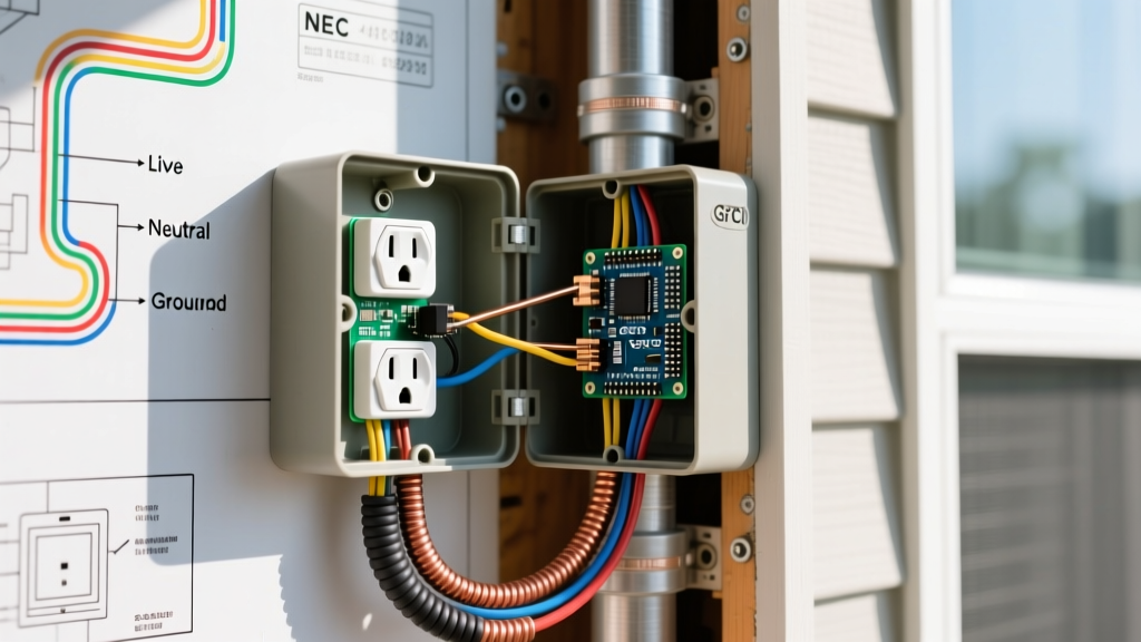
Inspect the exact mounting location. Is it under a covered porch (damp location) or fully exposed to the sky (wet location)? This distinction dictates your enclosure rating. According to the National Fire Protection Association (NFPA), wet locations require enclosures that are weatherproof whether or not the attachment plug is inserted.
Phase 2: Code-Compliant Component Selection
Inspectors will immediately fail an installation if the components do not match the environmental classification. In 2026, the standard for outdoor receptacles has evolved beyond basic plastic covers.
| Component | Minimum Code Requirement (NEC 2023/2026) | Recommended Pro-Grade Model | Estimated Cost |
|---|---|---|---|
| Receptacle | 20A GFCI, Weather-Resistant (WR) rating | Leviton TR725-W (20A WR GFCI) | $28 - $35 |
| Enclosure | Non-metallic or cast aluminum, NEMA 3R | Hubbell-Bell 1-Gang Non-Metallic Box | $12 - $18 |
| Cover | Extra-Duty (In-Use) Weatherproof Cover | TayMac MX850X Extra-Duty Die-Cast | $22 - $30 |
| Sealant | UV and Water Resistant Silicone | GE Silicone II Kitchen & Bath | $8 - $12 |
Inspector's Note: The term 'Extra-Duty' is not marketing fluff; it is a specific NEC classification (406.9(B)(1)) requiring the cover to accommodate a plug cap and cord while remaining fully closed and sealed. Standard flat covers are an automatic fail for wet locations.
Phase 3: The Installation & Sealing Protocol
While this is an inspection guide, the physical installation must meet specific measurable criteria to pass the testing phase.
- Conduit and Burial Depth: If running a new line, PVC conduit must be buried at least 18 inches deep. Direct burial UF-B cable requires 24 inches of cover. Inspectors will use a probe to verify depth before backfilling.
- Flange Sealing: Apply a continuous, 1/4-inch bead of GE Silicone II behind the weatherproof box flange before mounting it to the siding. Leave a 1-inch gap at the bottom of the flange to allow any trapped condensation to weep out.
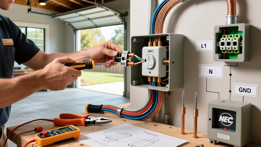
- Terminal Torque: NEC 110.14(D) mandates that connections be made using a calibrated torque tool. For a Leviton TR725-W with 12 AWG wire, set your torque screwdriver to exactly 14 in-lbs. Hand-tightening leads to thermal expansion loosening over time, causing arcing.
Phase 4: Post-Installation Testing Procedures
Once the wires are connected and the cover is secured, the testing phase begins. Do not rely on a simple lamp test; you must verify the electrical integrity and safety mechanisms of the circuit.
Step 1: GFCI Trip-Time and Fault Testing
Use a dedicated GFCI receptacle tester, such as the Klein Tools RT250. This device does more than just trip the outlet; it measures the exact millisecond trip time and verifies that the internal solenoid is functioning within UL standards.
- Correct Wiring Indication: Verify the LED sequence indicates 'Correct' (usually two amber lights, depending on the model).
- Ground Fault Simulation: Press the test button on the tester. The GFCI must trip within 25 milliseconds. If it takes longer, or fails to trip, the receptacle is defective or wired with a shared neutral from another circuit.
Step 2: Voltage Drop and Polarity Verification
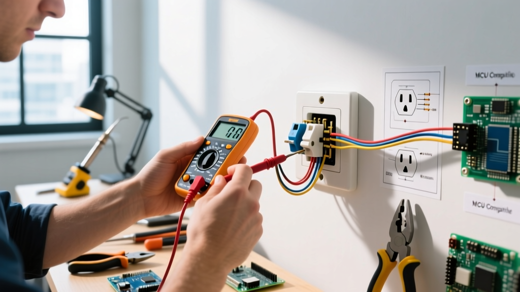
Outdoor outlets are often at the end of long wire runs. Use a digital multimeter (like the Fluke 117) to measure the voltage at the receptacle under load. Plug in a high-draw tool (e.g., a 1500W heat gun). The voltage should not drop below 110V on a standard 120V circuit. A drop below this threshold indicates undersized wiring or a poor connection upstream.
Step 3: The Water Ingress Simulation
Municipal inspectors frequently perform a 'hose test' or visually simulate water flow. With a cord plugged in and the in-use cover closed, spray water from a garden hose at a 45-degree downward angle for 5 minutes. Open the cover immediately after and inspect the internal GFCI test/reset buttons and the wire terminals with a flashlight. Any visible moisture means the cord grip seal or the flange caulk has failed.
Common Failure Modes and Edge Cases
Even with perfect installation, outdoor outlets present unique troubleshooting scenarios. Understanding these edge cases separates amateurs from experts.
Nuisance Tripping in High Humidity
If a newly installed outdoor GFCI trips randomly during morning dew or high humidity, the issue is rarely the GFCI itself. It is usually a downstream device or a microscopic nick in the wire insulation allowing micro-amps of current to leak to ground. The Electrical Safety Foundation International (ESFI) notes that GFCIs are designed to trip at a 4 to 6 milliamp leakage threshold. Inspect all downstream connections and ensure wire nuts are sealed with liquid electrical tape or silicone grease.
UV Degradation of Non-Metallic Boxes
Cheap, big-box-store plastic weatherproof boxes often lack adequate UV inhibitors. Within two years, the plastic becomes brittle and cracks, compromising the NEMA rating. Always inspect the box for a 'UV Resistant' or 'NEMA 3R' stamp. If replacing an old box, upgrade to a die-cast aluminum hub or a high-impact polycarbonate box rated for extreme temperatures.
Final Inspector Checkpoints Summary
Before calling for your municipal rough-in or final inspection, run through this definitive checklist to ensure a first-time pass:
- [ ] Receptacle is marked 'WR' (Weather Resistant) on the yoke.
- [ ] Cover is 'Extra-Duty' and fully encloses the plugged-in cord.
- [ ] Silicone bead is continuous behind the box, with a weep hole at the bottom.
- [ ] Torque screwdriver used for all terminal connections (14 in-lbs).
- [ ] GFCI tester confirms trip time under 25ms.
- [ ] No shared neutrals on multi-wire branch circuits feeding the exterior.
By treating the installation of an outdoor receptacle as a comprehensive system requiring rigorous inspection and testing, you ensure long-term reliability. For further reading on outdoor electrical hazards and safety protocols, consult the U.S. Consumer Product Safety Commission (CPSC) guidelines on exterior electrical safety. Mastering these protocols guarantees your outdoor power access is both highly functional and unequivocally safe.