
The Critical Role of Receptacle Terminals
When examining a standard 15-amp or 20-amp duplex receptacle, understanding the purpose of the electrical outlet gold and silver screws is the difference between a safe installation and a severe fire hazard. While modern smart home tech and USB-integrated outlets dominate the 2026 market, the foundational physics of alternating current (AC) wiring remains unchanged. Polarity matters. Reversing the hot and neutral connections can leave appliances energized even when switched off, creating a hidden shock risk.
In this comprehensive guide, we will break down the exact anatomy of a standard NEMA 5-15R and 5-20R receptacle, outline the professional tools required for a code-compliant installation, and provide a meticulous step-by-step wiring procedure.
Anatomy of a Standard Receptacle: Decoding the Screws
A standard Leviton 5262-SW or Eaton TR5262W duplex receptacle features three distinct terminal zones. The National Electrical Code (NEC) Article 406.4 strictly mandates proper identification and connection of these terminals to ensure grounded and polarized circuits.
| Screw Color | Wire Color (Standard) | Function | NEC Terminal Designation | Screw Thread Size |
|---|---|---|---|---|
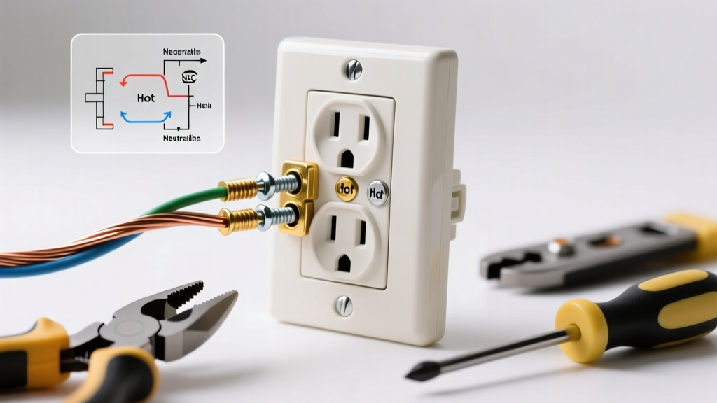
| Gold / Brass | Black, Red, or Blue | Hot / Line | Un-grounded Conductor | #10-32 |
| Silver | White or Gray | Neutral | Grounded Conductor | #10-32 |
| Green | Bare Copper or Green | Ground | Equipment Grounding | #10-32 |
Pro Tip: The brass/gold screws are typically located on the side of the receptacle with the shorter slot (the hot side), while the silver screws align with the longer slot (the neutral side). This physical alignment ensures proper polarization when plugging in devices.
Essential Tools for 2026 Installations
Do not rely on outdated or multi-purpose tools for electrical terminations. A professional-grade setup ensures precise strip lengths and secure torque, preventing arc faults down the line.
- Wire Strippers: Klein Tools 11055 (for 10-18 AWG solid/stranded). Precise gauge holes prevent nicking the copper conductor.
- Non-Contact Voltage Tester: Fluke 1AC-II VoltAlert or Milwaukee 2202-20. Essential for verifying a dead circuit before touching bare metal.
- Torque Screwdriver: Klein Tools 32500 or a dedicated inch-pound dial. As of the 2023 NEC (widely enforced in 2026), terminations must be torqued to manufacturer specifications, typically 14 in-lbs for standard 15A/20A receptacles.
- Lineman Pliers: For bending perfect J-hooks and trimming excess copper.
Step-by-Step Installation Guide
Step 1: De-energize and Verify
Locate your main electrical panel and switch off the breaker controlling the circuit. Use your Fluke non-contact tester to verify the absence of voltage at the existing outlet. Test a known live circuit first to confirm your tester's battery is functioning. Remove the faceplate and unscrew the receptacle from the junction box, pulling it out gently without touching the side terminals.
Step 2: Prepare the Conductors
Proper wire preparation is where most DIY failures occur. Using the gauge hole on your Klein wire strippers, strip exactly 3/4 inch (19mm) of insulation from the black, white, and bare copper wires. Most modern receptacles feature a built-in strip gauge on the back of the yoke; use it. If the copper is scored or nicked during stripping, cut it back and try again. A nicked wire will snap when bent and create a high-resistance hot spot.
Step 3: Terminate the Ground (Green Screw)
Form a J-hook in the bare copper wire using your lineman's pliers. The hook must curve clockwise. Wrap it around the green grounding screw at the bottom or center of the receptacle. As you tighten the screw clockwise, the hook will naturally pull tighter around the shaft. Torque to 14 in-lbs. If you are using a metal junction box, ensure a grounding pigtail also connects the box to the ground wire bundle using a green wire nut or copper crimp.
Step 4: Terminate the Neutral (Silver Screw)
Identify the white neutral wire. Form a clockwise J-hook and attach it to one of the silver screws. Ensure no bare copper extends past the screw head (which could cause a short), and that no insulation is trapped under the screw washer (which causes a high-resistance connection). According to the Consumer Product Safety Commission (CPSC), loose neutral connections are a leading cause of residential electrical fires due to arcing and heat buildup.
Step 5: Terminate the Hot (Gold/Brass Screw)
Take the black (hot) wire and form your clockwise J-hook. Attach it to one of the gold/brass screws. Again, verify the clockwise orientation. Tightening the screw should close the loop, not push it outward. If the loop opens as you tighten, the wire can slip out from under the screw head, resulting in a catastrophic arc fault.
Step 6: Secure, Dress, and Test
Carefully fold the wires into the back of the junction box. Push the ground wires in first, followed by the neutrals, and finally the hot wires. Align the receptacle with the box ears and secure it with the provided #6-32 mounting screws. Attach the faceplate, restore power at the breaker, and test the outlet using a 3-prong receptacle tester (like the Gardner Bender GFI-6302) to confirm correct wiring and GFCI functionality if applicable.
Side-Wiring vs. Push-In (Backstab) Terminals
Many commercial-grade and residential receptacles feature push-in (backstab) terminals on the rear, alongside the traditional side-wire screws. While the NEC and OSHA wiring standards permit their use for 14 AWG solid wire, professional electricians almost universally avoid them.
Push-in terminals rely on a small internal spring-steel clamp that grips the wire. Over time, thermal expansion and contraction from electrical loads can cause these springs to relax, leading to high-resistance connections, melting, and fires. Always use the side-wire gold and silver screws or the screw-clamp (back-wire) plates found on premium spec-grade receptacles. Side-wiring provides a massive surface area contact and mechanical security that push-in terminals simply cannot match.
Common Edge Cases and Troubleshooting
Split Receptacles and Multi-Wire Branch Circuits
In kitchens and living rooms, you may encounter a split receptacle where the top half is controlled by a wall switch and the bottom half is always hot. This is achieved using two separate hot wires (often black and red) connected to the two gold screws. To wire this correctly, you must break the brass connecting tab between the two gold screws using needle-nose pliers. If you fail to break this tab, you will create a dead short between the two breakers, resulting in an immediate trip or a dangerous fault. Never break the silver tab unless you are working with a highly specific, rare multi-wire neutral setup.
Reversed Polarity
If your 3-prong tester indicates "Hot/Neutral Reverse," you have connected the black wire to the silver screw and the white wire to the gold screw. This is a critical violation of National Fire Protection Association (NFPA) codes. While the device will still power on, the internal switch of the appliance will only disconnect the neutral path, leaving the internal components fully energized at 120V. Turn off the breaker, swap the wires to their correct gold and silver screws, and retest.
Frequently Asked Questions
Can I connect two wires to a single gold or silver screw?
No. The NEC strictly prohibits terminating more than one wire under a single terminal screw unless the receptacle is explicitly listed and identified for such use (which standard 15A/20A duplex receptacles are not). If you need to daisy-chain power to a downstream outlet, use a wire nut or a Wago 221 lever connector to pigtail the wires, then run a single jumper wire to the receptacle screw.
What happens if the J-hook is bent counter-clockwise?
If the hook is counter-clockwise, the rotational force of tightening the screw will push the wire loop outward and away from the screw head. This reduces the contact surface area, increases electrical resistance, and generates excess heat under load. Always bend clockwise.
Do I need to use the green ground screw if the box is metal?
Yes. While a metal box can serve as a grounding path via the mounting screws or grounding clips, best practice and modern code interpretations require a dedicated equipment grounding conductor (EGC) connected directly to the receptacle's green screw to ensure a low-impedance fault path.
Final Thoughts
Mastering the termination of electrical outlet gold and silver screws is a fundamental skill for any DIYer or apprentice electrician. By prioritizing side-wiring over backstabbing, adhering to precise strip lengths, and utilizing a torque screwdriver, you ensure your 2026 electrical installations are not only code-compliant but built to last decades without thermal degradation.