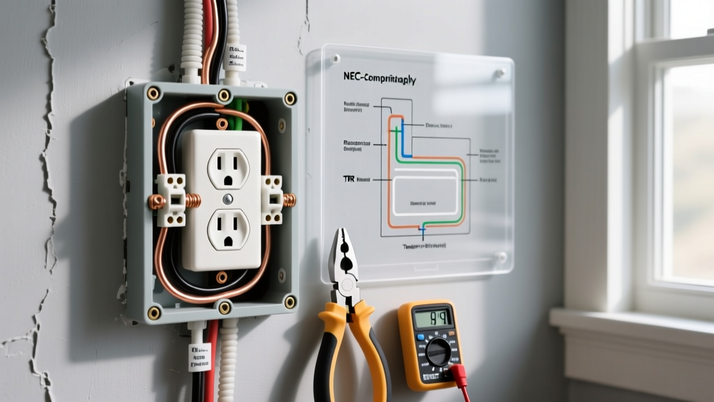

The Physics of Heat: Why Your Electrical Outlet is Warm to the Touch
Human skin is remarkably sensitive to thermal changes; the average person registers a surface as "warm to the touch" at approximately 95°F (35°C). When an electrical outlet warm to the touch is discovered, it is rarely a benign anomaly. From a wiring diagram perspective, heat is the physical manifestation of electrical resistance. According to Joule's First Law ($P = I^2R$), heat generation in a circuit is proportional to the square of the current multiplied by the resistance. In a properly functioning 15-amp or 20-amp branch circuit, resistance at the receptacle terminals should be near zero. When an outlet feels warm, the wiring configuration has introduced unintended resistance, or the circuit topology is forcing excessive current through the receptacle's internal bus bars.
As of the 2026 National Electrical Code (NEC) updates and modern UL 498 manufacturing standards, receptacles are designed to handle specific thermal loads. However, improper wiring topologies—specifically daisy-chaining high-draw appliances and utilizing deprecated push-in terminals—routinely bypass these safety margins. This guide decodes the wiring diagrams behind outlet heating, providing actionable diagnostics and precise remediation steps for DIYers and electricians alike.
Thermal Diagnostics: Safe vs. Dangerous Temperature Ranges
Before tearing into a wiring diagram, establish a baseline using an infrared (IR) thermometer, such as the Klein Tools IR10. The National Fire Protection Association (NFPA) warns that electrical fires often originate from smoldering connections long before a breaker trips. Use the matrix below to interpret your IR readings relative to standard ambient room temperature (assumed 72°F / 22°C).
| Surface Temperature | Thermal Delta (ΔT) | Wiring Diagram Diagnosis | Action Required |
|---|---|---|---|
| 72°F - 85°F | +0°F to +13°F | Normal operating temperature for loaded circuits (e.g., TV, router). | None. Monitor annually. |
| 86°F - 105°F | +14°F to +33°F | Mild resistance. Likely a loose screw terminal or early-stage backstab failure. | Schedule inspection. Tighten terminals to spec. |
| 106°F - 130°F | +34°F to +58°F | Critical resistance. Arcing, oxidized aluminum, or daisy-chain overload. | Immediate shutdown. Rewire using pigtail diagram. |
| > 130°F | > +58°F | Imminent failure. Melting PVC insulation, severe bus bar degradation. | Emergency breaker trip. Replace receptacle and wiring. |
Wiring Diagram Fault 1: The "Backstab" Push-In Terminal Failure
The most common cause of an electrical outlet warm to the touch in homes built or renovated between 1990 and 2015 is the use of "backstab" or push-in wiring terminals. In a standard backstab wiring diagram, the stripped 14 AWG solid copper wire is pushed into a rear hole where a razor-thin internal spring steel clip bites into the wire.
The Mechanical Failure Mode
Unlike a screw terminal, which wraps the wire 270 degrees around a brass cylinder to maximize surface area contact, the backstab clip relies on a microscopic point of contact. Over years of thermal cycling (expansion and contraction from daily load changes) and mechanical vibration (plugging and unplugging cords), the spring steel loses its tension. This increases the micro-gap between the wire and the clip, spiking electrical resistance. The resulting $I^2R$ heating warms the rear of the receptacle and can eventually melt the polycarbonate housing.
Expert Rule: The 2026 NEC and best practices dictate that push-in terminals should never be used for 15A or 20A receptacles, regardless of whether the manufacturer still includes them on budget models like the basic Leviton 5320-WMP. Always use the side screw terminals or rear clamp plates found on commercial-grade models like the Hubbell 5262.
Wiring Diagram Fault 2: Daisy-Chain Overload (The Load Bus Bar)
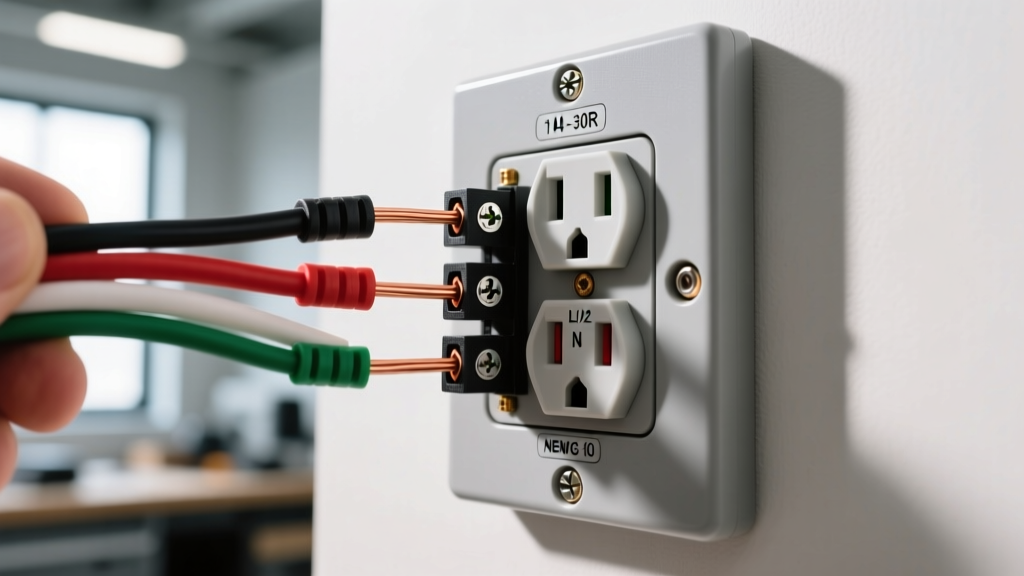
A standard duplex receptacle features two brass (hot) screws and two silver (neutral) screws. In a "daisy-chain" wiring diagram, the incoming power (Line) connects to one set of screws, and the outgoing power to the next outlet (Load) connects to the second set. The internal brass bus bar bridges the Line screw to the Load screw.
The Continuous Load Problem
If you plug a 1,500W space heater (drawing ~12.5 Amps) into the downstream outlet, that entire 12.5A current must travel through the upstream receptacle's Line terminal, across its internal brass bus bar, and out the Load terminal to reach the heater. While 12.5A is technically below the 15A breaker threshold, the NEC defines this as a "continuous load" if it runs for 3 hours or more. Continuous loads generate sustained thermal buildup. If the upstream receptacle is a budget builder-grade model with thin internal bus bars, the metal will act as a resistor, turning the outlet warm to the touch.
- Line Side Heat: Indicates the total cumulative load of the entire daisy-chain is stressing the incoming wire or terminal.
- Load Side Heat: Indicates the downstream devices are pulling heavy current through the receptacle's internal bridge.
Wiring Diagram Fault 3: Loose Neutrals and High-Resistance Joints
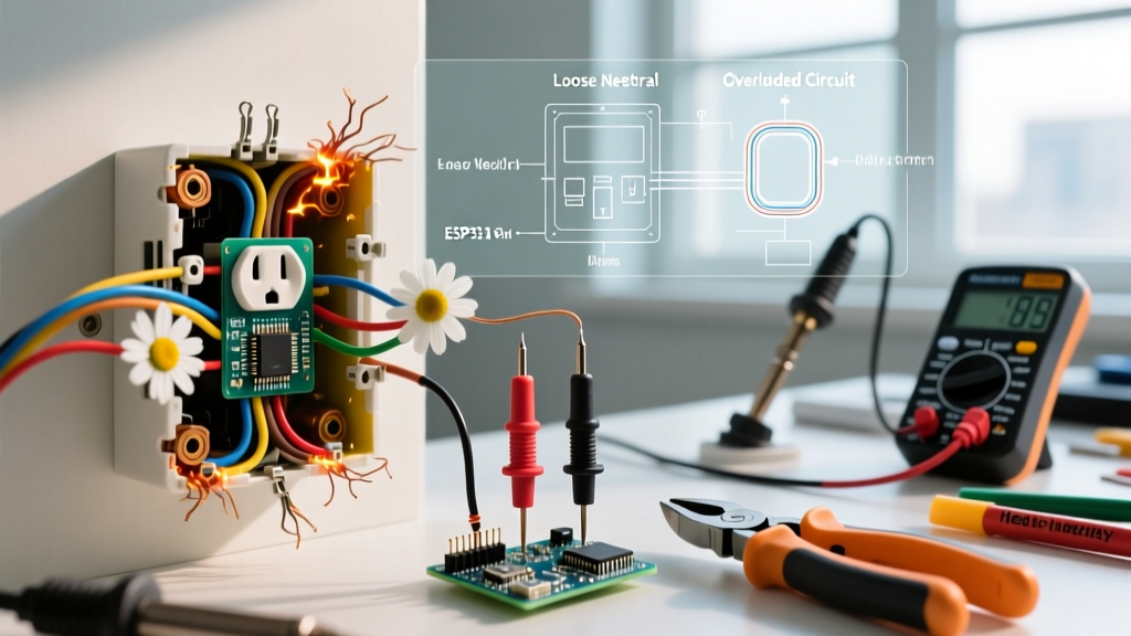
While hot (brass) side faults are dangerous, a loose neutral (silver side) connection is arguably more insidious. In a 120V circuit, the neutral carries the exact same return current as the hot wire. If the neutral wire is not seated deeply under the screw terminal, or if the wire nut connection in the back of the box is loose, resistance skyrockets. Furthermore, if your home utilizes legacy aluminum wiring (pre-1972), aluminum creeps and oxidizes rapidly under standard brass screw terminals, creating aluminum oxide—a highly resistive ceramic-like compound that traps heat inside the junction box.
For aluminum wiring remediation, standard receptacles are illegal and unsafe. You must use CO/ALR (Copper-Aluminum Revised) rated receptacles, which feature specialized screw alloys and deeper wire loops to prevent galvanic corrosion and thermal creep.
The Superior Wiring Diagram: Pigtailing vs. Daisy-Chaining
To permanently eliminate bus-bar heating and isolate receptacles from downstream fault currents, master electricians utilize the Pigtail Wiring Diagram. Instead of routing the downstream circuit through the receptacle's internal metal straps, you connect the Line and Load wires together using a wire nut (or lever nut like the WAGO 221), along with a short 6-inch "pigtail" wire. This pigtail is the only wire connected to the receptacle's screw terminal.
Why Pigtailing Solves Thermal Issues
- Bypasses the Bus Bar: Downstream current flows directly from the Line wire to the Load wire via the wire nut, completely bypassing the receptacle's internal brass bridge.
- Isolates Failures: If the receptacle fails or is removed, the downstream outlets remain powered because the circuit continuity is maintained in the wire nut, not the device.
- Reduces Box Clutter: Using WAGO 221 lever connectors for pigtailing reduces the physical bulk in the junction box, improving ambient air circulation and heat dissipation.
Step-by-Step Remediation & 2026 Torque Specifications
If your outlet is warm, follow this precise remediation protocol to restore safety and code compliance.
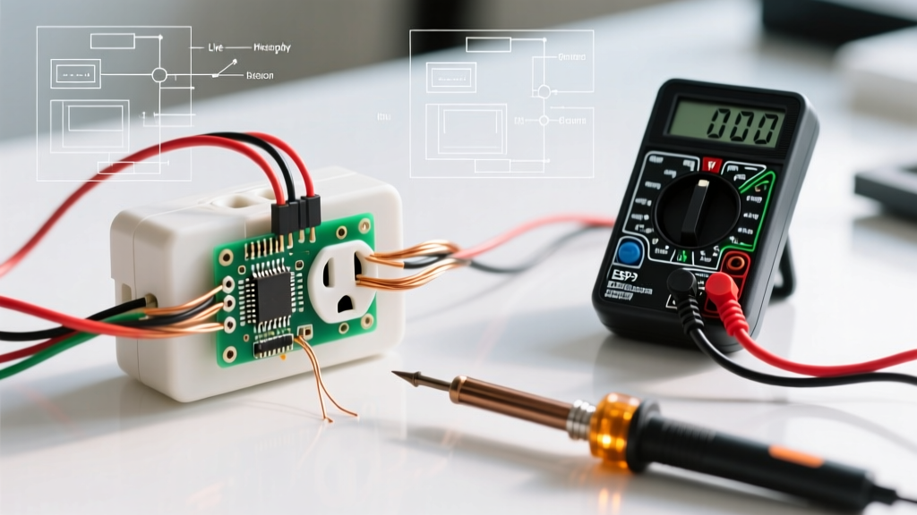
- Kill the Power & Verify: Turn off the breaker and verify 0V using a non-contact voltage tester (e.g., Fluke 2AC) and a multimeter.
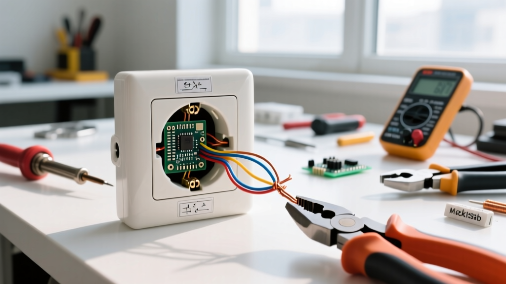
- Extract and Inspect: Pull the receptacle from the box. Look for brown scorch marks, melted PVC, or brittle wire insulation. If the wire insulation is cracked, strip it back to clean copper.
- Remove Backstabbed Wires: Never reuse a wire that has been pulled from a backstab terminal; the spring clip has likely scored and weakened the copper. Cut the end and re-strip 3/4 inch of insulation.
- Form the J-Hook: Using needle-nose pliers, form a tight "J-hook" in the solid copper wire. The hook must wrap clockwise around the screw so that tightening the screw pulls the loop closed, rather than pushing it out.
- Apply Exact Torque: The U.S. Consumer Product Safety Commission (CPSC) and modern NEC guidelines emphasize calibrated torque to prevent under-tightening (causing arcing) or over-tightening (shearing the screw head or deforming the wire). Use a torque screwdriver set to the manufacturer's spec—typically 12 in-lbs for 14 AWG and 14 in-lbs for 12 AWG copper wire.
- Secure the Yoke: Ensure the receptacle yoke sits flush against the drywall or plaster ring. A floating receptacle causes mechanical stress on the terminals every time a cord is plugged in, eventually loosening the screws and restarting the heating cycle.
Frequently Asked Questions (FAQ)
Can a warm outlet cause a fire even if the breaker doesn't trip?
Yes. Standard thermal-magnetic breakers are designed to trip on overcurrent (e.g., pulling 25A on a 15A circuit). They do not detect resistance. A loose connection drawing only 5 Amps can generate enough localized heat (hundreds of degrees at the micro-gap) to ignite surrounding wood framing or insulation without ever tripping the 15A breaker. This is why AFCI (Arc-Fault Circuit Interrupter) breakers are now mandated in most living spaces to detect the high-frequency signatures of arcing connections.
Is it normal for a dimmer switch or smart outlet to feel warm?
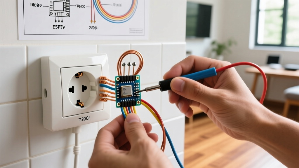
Yes, but with caveats. Solid-state devices like smart plugs (e.g., Kasa EP25) or dimmer switches contain internal TRIACs and power supplies that generate a small amount of waste heat. The U.S. Department of Energy notes that a slight warmth on the faceplate of a smart device is normal. However, if the heat is concentrated at the junction box screws or the plastic feels hot enough to be uncomfortable, the device is either overloaded or improperly wired.
Should I upgrade my 15A outlets to 20A to stop the heating?
No. Upgrading a 15A receptacle to a 20A receptacle (like a NEMA 5-20R) on 14 AWG wire is a severe NEC violation and a fire hazard. The 20A receptacle will not stop the heating if the wire gauge or circuit breaker is mismatched. The heat is caused by resistance or overload, not the receptacle's amperage rating. Always match the receptacle rating to the breaker and wire gauge (15A breaker/14 AWG wire = 15A receptacle; 20A breaker/12 AWG wire = 20A receptacle).