
The Evolution of the Electric Outlet with USB C
As of 2026, the standard 5W USB-A receptacle is practically obsolete in modern residential and commercial builds. The modern electric outlet with USB C leverages Power Delivery (PD 3.1) protocols to output anywhere from 20W to 30W directly from the wall, capable of fast-charging laptops, tablets, and flagship smartphones. However, integrating these high-draw DC power supplies into standard 15A and 20A AC branch circuits introduces unique thermal and spatial challenges that standard receptacles do not face.
This wiring diagram reference and installation guide covers the exact terminal mapping, National Electrical Code (NEC) box fill calculations, and critical edge cases you need to know before installing a USB-C combo receptacle. Whether you are upgrading a single gang box in a bedroom or wiring a multi-port hub in a commercial office, understanding the internal architecture of these devices is mandatory for a safe, code-compliant installation.
Anatomy of a USB-C PD Receptacle
Unlike a standard duplex receptacle that simply passes AC current through brass and nickel-plated steel contacts, an electric outlet with USB C houses a complex internal switching power supply. This internal transformer steps down 120V AC to 5V/9V/15V DC, which inherently generates waste heat.
Key Internal Components
- AC Terminals: Standard brass (hot) and silver (neutral) screws for 14 AWG or 12 AWG copper conductors.
- Switching Power Supply Module: Located in the rear yoke, converting AC to DC. This makes the chassis significantly deeper than a standard outlet.
- PD Negotiation Chip: Communicates with plugged-in devices to safely negotiate wattage (e.g., 25W for a smartphone, 30W for a tablet).
- Thermal Shutoff Relay: A critical safety feature in 2026-compliant UL-listed models that cuts DC power if internal temperatures exceed 85°C (185°F).
Wiring Diagram & Terminal Mapping
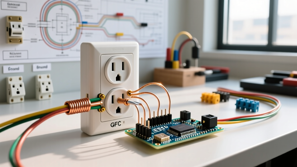
The most common point of failure for electricians and DIYers transitioning from standard or GFCI outlets to USB-C outlets is the search for a LOAD terminal. Most USB-C receptacles do not have LOAD terminals.
CRITICAL WIRING WARNING: The internal USB power supply is a parallel load on the circuit. It does not pass DC power downstream. Furthermore, many manufacturers (including Leviton and Hubbell) omit AC LOAD terminals entirely to prevent downstream overloading of the internal heat sink. If you need to feed power to a downstream outlet, you MUST use pigtails to connect both the downstream cable and the USB outlet to the LINE source.
Standard 15A/20A Terminal Mapping
| Terminal Type | Screw Color | Wire Connection | Wire Gauge Accepted |
|---|---|---|---|
| LINE Hot | Brass | Black (or Red) Insulated Wire | 14 AWG - 12 AWG |
| LINE Neutral | Silver | White Insulated Wire | 14 AWG - 12 AWG |
| Ground | Green | Bare Copper or Green Wire | 14 AWG - 12 AWG |
NEC Box Fill Calculations (Article 314.16)
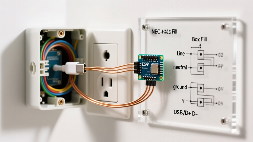
Because the internal transformer of a USB-C outlet takes up significant physical space, you must adhere strictly to NEC Article 314.16 box fill calculations. According to the National Fire Protection Association (NFPA 70), a single device yoke counts as two wire volumes based on the largest wire connected to the device.
Calculation Example: 12 AWG Circuit (20A)
- Device Volume: 2 x 2.25 cu in = 4.5 cu in
- Hot & Neutral Wires (2 entering): 2 x 2.25 cu in = 4.5 cu in
- Ground Wires (all combined): 1 x 2.25 cu in = 2.25 cu in
- Internal Clamps: 1 x 2.25 cu in = 2.25 cu in
- Total Minimum Box Volume Required: 13.5 cu in
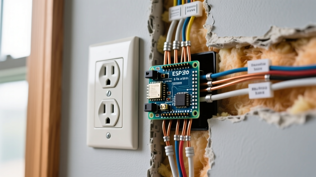
While a standard 18 cu in single-gang box technically meets the mathematical minimum, the physical depth of the USB-C chassis (often 1.6 inches or more) will make folding 12 AWG wire extremely difficult, leading to crushed conductors and heat trapping. Best Practice: Always use a 22.5 cu in deep single-gang box (at least 2.5 inches deep) for any electric outlet with USB C.
Step-by-Step Wiring Guide
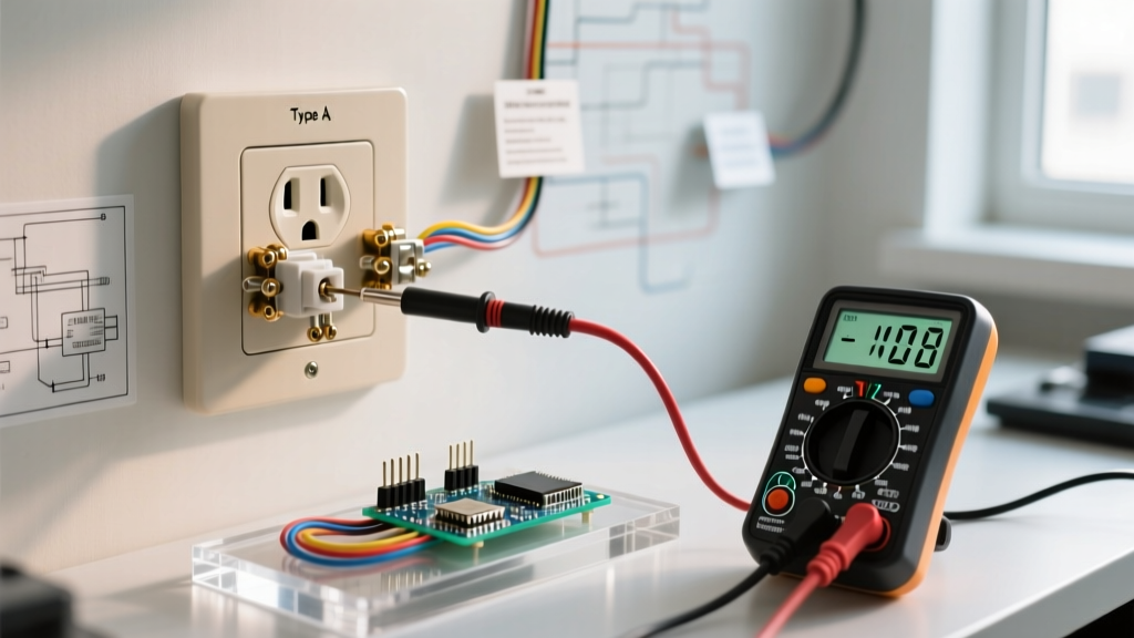
- De-energize and Verify: Turn off the breaker. Use a non-contact voltage tester (NCVT) and a multimeter to confirm 0V at the receptacle.
- Strip the Conductors: Use the built-in strip gauge on the back of the USB-C receptacle. For 12 AWG solid copper, this is typically 5/8 inch (16mm). Do not over-strip; exposed copper outside the terminal yoke is a shock hazard.
- Pigtail if Feeding Downstream: If this outlet is in the middle of a run, use wire nuts or push-in connectors (like Wago 221) to pigtail the incoming and outgoing hot/neutral wires. Connect the pigtails to the LINE terminals on the USB outlet.
- Terminate and Torque: Wrap the wire clockwise around the terminal screw. While NEC 110.14(D) mandates torque screwdrivers primarily for high-amperage terminations, manufacturer specs for high-draw PD modules often recommend tightening terminal screws to 14 in-lbs to prevent voltage drop and arcing under continuous DC loads.
- Fold and Mount: Carefully fold the grounding wires into the back of the box first, followed by the neutral, then the hot wires. Push the heavy USB chassis in evenly to avoid pinching wires against the metal box edges.
Model Comparison Matrix (2026 Market)
Not all USB-C outlets are created equal. Below is a comparison of the most common UL-listed receptacles available for residential and commercial wiring.
| Manufacturer & Model | USB-C Output | USB-A Output | Avg. Price | Best Application |
|---|---|---|---|---|
| Leviton T5636 | 25W PD | 2x 12W | $38 - $45 | Bedrooms, Home Offices |
| Hubbell USB20W3C | 20W PD | None (Type-C only) | $42 - $50 | Modern Commercial, Kitchens |
| Cooper TR7745 | 15W PD | 1x 12W | $28 - $34 | Guest Rooms, Budget Upgrades |
Troubleshooting & Edge Cases
Issue: The USB-C Port Charges Slowly or Intermittently
Diagnosis: Thermal throttling or voltage drop. If the outlet is installed in a shallow plastic box surrounded by blown-in insulation, the internal thermal relay will throttle the PD output from 25W down to 5W to prevent a fire. Solution: Upgrade to a metal single-gang box. Metal acts as a passive heatsink, drawing waste heat away from the switching power supply and allowing the PD chip to maintain maximum wattage. Ensure the wall plate has adequate ventilation gaps.
Issue: Tripping AFCI/GFCI Breakers Upon Insertion
Diagnosis: Inrush current. When a device with a massive battery (like a laptop) is plugged into a USB-C PD port, the initial inrush current to the internal capacitors can sometimes mimic a ground fault or arc fault to highly sensitive 2026-era AFCI/GFCI breakers. Solution: Ensure the circuit is not overloaded. If the issue persists on a specific breaker brand, consult the breaker manufacturer's compatibility list for high-capacitance DC power supplies. The U.S. Consumer Product Safety Commission (CPSC) recommends ensuring all Tamper-Resistant (TR) shutters are fully clearing the plug prongs to prevent micro-arcing that triggers AFCI sensors.
Issue: Downstream Outlets are Dead
Diagnosis: You wired the downstream cables to the USB outlet, assuming it had LOAD terminals like a GFCI. Solution: Remove the outlet, identify the line and load cables using a voltage tester, and wire them together using pigtails. The USB outlet must be wired in parallel with the downstream feed, not in series.
Energy Efficiency and Phantom Loads
Modern USB-C receptacles are highly efficient, but they do draw a phantom load when no devices are plugged in. According to the U.S. Department of Energy (DOE), managing standby power is crucial for whole-home efficiency. A high-quality 2026 USB-C outlet with an auto-shutoff feature will draw less than 0.05W when idle. Cheaper, non-UL-listed imports can draw up to 1.5W continuously, generating unnecessary heat and wasting electricity. Always verify the UL mark and look for 'No-Load Auto Shutoff' on the specification sheet before purchasing.
Final Safety Checklist
- Verify the circuit breaker amperage matches the wire gauge (15A for 14 AWG, 20A for 12 AWG).
- Ensure the receptacle is marked 'TR' (Tamper Resistant) as required by NEC 406.12 for all residential 15A and 20A receptacles.
- Confirm the wall box depth is at least 2.5 inches to accommodate the deep chassis and prevent wire crushing.
- Use a calibrated torque screwdriver to secure terminal screws to manufacturer specifications.