
The Reality of the '110 Electrical Outlet' in Modern Homes
If you are searching for how to wire a 110 electrical outlet, you are likely looking at a standard household receptacle. However, before we pick up a screwdriver, we need to address a critical terminology shift in the electrical industry. While homeowners and older DIY guides still colloquially refer to standard outlets as '110V', the actual nominal voltage delivered by the modern North American power grid is 120V. The National Electrical Code (NEC) and utility companies standardized this shift decades ago to account for voltage drop over distance, meaning your '110 electrical outlet' is actually a 120V, 15-amp or 20-amp duplex receptacle.
Understanding this distinction is vital when purchasing materials at your local hardware store. Receptacles are universally rated for 125V to provide a safety buffer above the 120V nominal supply. In this comprehensive beginner's tutorial, we will walk you through the exact process of safely replacing or installing a standard 120V (110V) receptacle, adhering to the latest 2023/2026 NEC safety standards, and avoiding the most common pitfalls that lead to arcing and electrical fires.
Essential Tools and Materials Matrix
Working with residential branch circuits requires precision. Using the wrong wire strippers can nick the copper conductor, creating a weak point that heats up under load. Below is the exact toolkit we recommend for a standard 15A outlet installation.
| Category | Recommended Item | Specific Model / Spec | Estimated Cost |
|---|---|---|---|
| Receptacle | 15A Tamper-Resistant Duplex | Leviton R52-05325-00W (125V) | $1.50 - $2.50 |
| Voltage Tester | Non-Contact Voltage Tester | Milwaukee 2202-20 | $15.00 - $20.00 |
| Wire Strippers | Precision Stripper/Cutter | Klein Tools 11054E (14-12 AWG) | $25.00 - $30.00 |
| Screwdriver | Insulated Phillips/Flathead | Klein Tools 32500INS | $12.00 - $15.00 |
| Wire Connectors | Push-In Wire Connectors | IDEAL In-Sure 3-Port (if pigtailing) | $0.25 each |
Phase 1: Safety and Circuit Verification
According to the Occupational Safety and Health Administration (OSHA), electrical incidents are a leading cause of workplace and residential injuries. Never assume a wire is dead just because a lamp plugged into the outlet is off.
- Locate the Breaker: Go to your main electrical panel and identify the breaker controlling the room. If your panel is not labeled, use a radio or lamp plugged into the target outlet and flip breakers until the device powers down.
- Lockout/Tagout (LOTO): Place a piece of electrical tape over the breaker switch and write 'DO NOT TOUCH - WORKING ON WIRING' to prevent another household member from accidentally restoring power while your hands are in the box.
- Verify with a Tester: Remove the existing wall plate. Insert your non-contact voltage tester (NCVT) into the slots of the receptacle and hold it against the side of the outlet where the wires connect. The tester must remain completely silent and unlit.
Phase 2: Step-by-Step Wiring Procedure
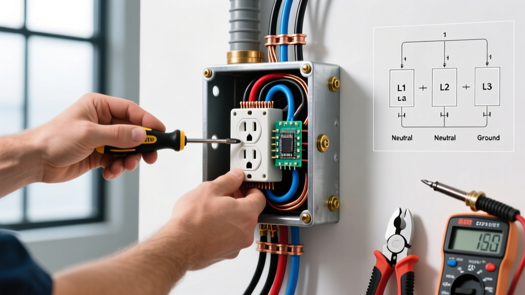
Once power is verified off, remove the top and bottom mounting screws holding the old receptacle to the electrical box. Gently pull the receptacle out to expose the wiring.
Step 1: Inspect and Prepare the Conductors
Examine the exposed copper on the black (hot), white (neutral), and bare/green (ground) wires. If the copper is deeply grooved, oxidized, or brittle from a previous 'backstab' connection, use your Klein Tools wire strippers to snip off the damaged ends. Re-strip exactly 3/4 of an inch of insulation using the built-in gauge on the side of your new Leviton receptacle. Exposing too much copper creates a shock hazard; exposing too little results in insulation being trapped under the screw terminal, causing a high-resistance connection.
Step 2: Form the Shepherd's Hook
Using needle-nose pliers, bend the stripped end of each wire into a tight, clockwise hook. The clockwise direction is non-negotiable. When you tighten the terminal screw, the clockwise rotation of the screw will pull the hook tighter around the shaft. A counter-clockwise hook will be pushed outward as the screw turns, leading to a loose connection.
Step 3: Make the Terminations
Connect the wires to their respective terminals on the new 110 electrical outlet:
- Ground (Green Screw): Connect the bare copper or green wire first. This provides a stable physical anchor.
- Neutral (Silver Screw): Connect the white wire to the silver terminal.
- Hot (Brass Screw): Connect the black wire to the brass terminal.
Step 4: Torque and Secure
Tighten each screw firmly. While NEC 110.14(D) mandates specific torque values for larger commercial connections, residential 15A receptacles generally require between 14 and 16 inch-pounds of torque. Give each screw a firm final turn until snug, but do not overtighten to the point of stripping the brass threads. Give each wire a firm tug to ensure it is mechanically locked.
Advanced Technique: The Pigtail Method for Downstream Outlets
If your electrical box contains two sets of cables (two blacks, two whites, two grounds), your outlet is feeding power to another downstream outlet. Do not use the receptacle's terminal screws to splice the wires. If the receptacle fails or is removed, the downstream circuit will lose its neutral or hot feed, creating a dangerous floating neutral scenario.
Instead, use the pigtail method. Splice the two incoming and outgoing hot wires together with a 6-inch piece of black wire (the pigtail) using an IDEAL In-Sure push-in connector. Repeat for the neutral and ground wires. Connect only the single pigtail ends to the receptacle screws. This ensures the circuit remains intact regardless of the receptacle's status.
NEC Code Compliance and Common Beginner Mistakes
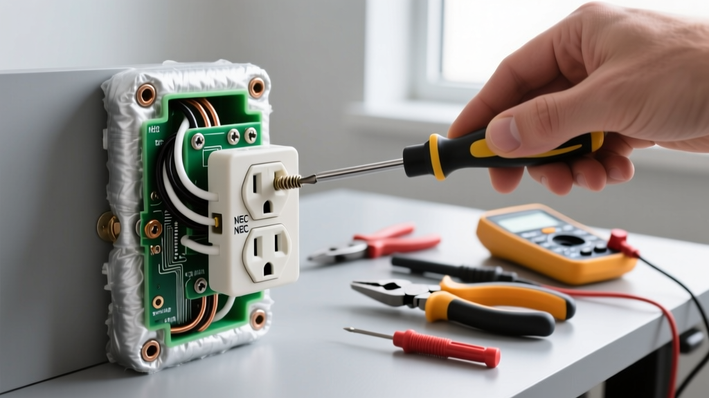
Critical Code Update: Under NEC Article 406.12, all 15A and 20A, 125V receptacles installed in dwelling units must be Tamper-Resistant (TR). TR receptacles feature internal shutters that only open when equal pressure is applied to both slots simultaneously, preventing children from inserting foreign objects. Always look for the 'TR' stamp on the face of the receptacle.
Mistake 1: Using 'Backstab' Push-In Connectors
Many budget receptacles feature small holes on the back for quick push-in wiring. Avoid these at all costs. The internal spring-metal clips degrade over time due to thermal expansion and contraction, leading to arcing and melted plastic. Always use the side-wiring screw terminals described in Step 3.
Mistake 2: Reversing Hot and Neutral (Polarity)
Connecting the black wire to the silver screw and the white wire to the brass screw creates a reversed polarity condition. While the device plugged into the outlet will still function, the internal switch of the appliance will now interrupt the neutral path instead of the hot path, leaving internal components energized and posing a severe shock hazard during maintenance.
Mistake 3: Box Overcrowding
NEC Article 314.16 dictates strict box fill calculations. A standard single-gang box (18 cubic inches) can comfortably hold one receptacle and two 14/2 NM cables. If you are pigtailing multiple wires in a shallow 12.5 cubic inch 'old work' box, you risk crushing the drywall and damaging wire insulation. Always upgrade to a 20+ cubic inch deep box if extensive pigtailing is required.
Frequently Asked Questions
Can I install a 20A receptacle on a 15A breaker?
While a 20A receptacle (identified by a T-shaped neutral slot) can physically handle a 15A load, it is generally a violation of NEC Article 210.21(B)(3) to install a single 20A receptacle on a 15A circuit. If you have a standard 15A breaker, stick to standard 15A duplex receptacles to prevent a false sense of capacity for whoever plugs in a high-draw appliance later.
When is a GFCI required instead of a standard 110 outlet?
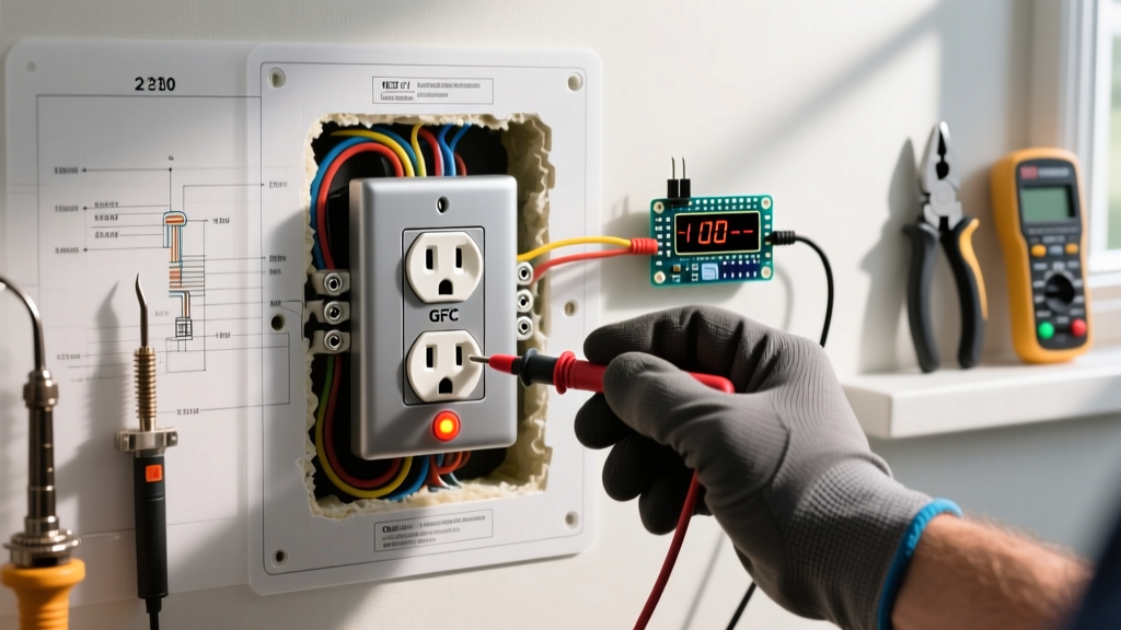
According to the National Fire Protection Association (NFPA) and NEC Article 210.8, Ground Fault Circuit Interrupter (GFCI) protection is mandatory in areas with water proximity. This includes bathrooms, kitchens (countertop circuits), garages, unfinished basements, laundry areas, and all outdoor receptacles. For these locations, you must install a GFCI receptacle, not a standard duplex outlet.
Why is my new outlet not sitting flush against the wall?
This is usually caused by drywall mud buildup inside the electrical box or a box that was set too deep. Do not simply overtighten the mounting screws, as this will warp the plastic yoke of the receptacle and cause the internal contacts to bind. Instead, use plastic receptacle shims (outlet spacers) wrapped around the mounting screws to bridge the gap between the outlet yoke and the drywall surface.
By following this precise methodology, you ensure your 110 electrical outlet installation is not only functional but meets the rigorous safety standards expected in modern residential wiring. For further reading on residential electrical safety and tamper-resistant technologies, consult the resources provided by the Electrical Safety Foundation International (ESFI).