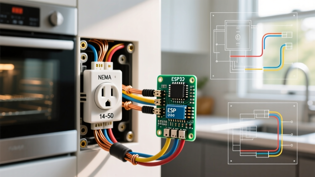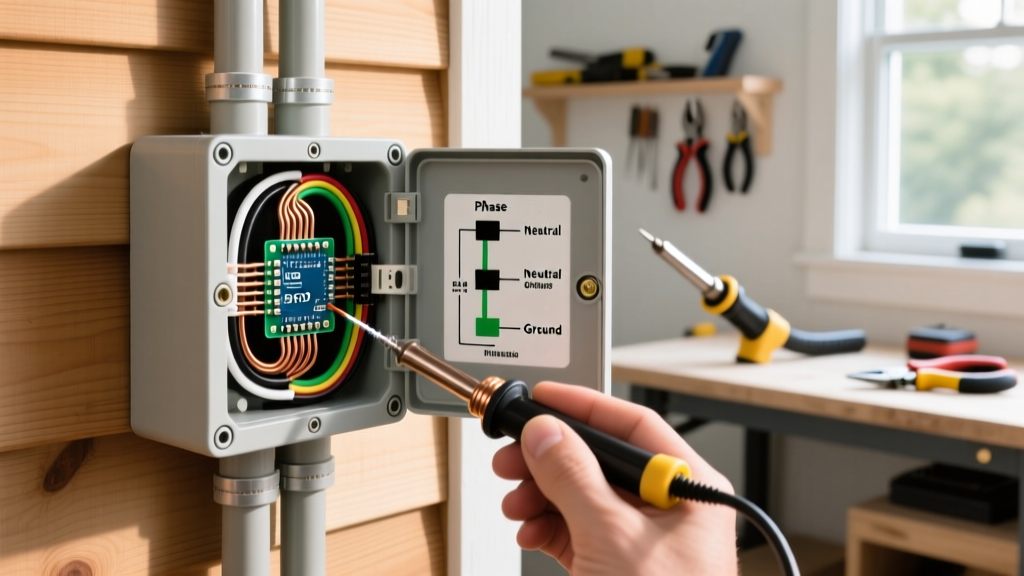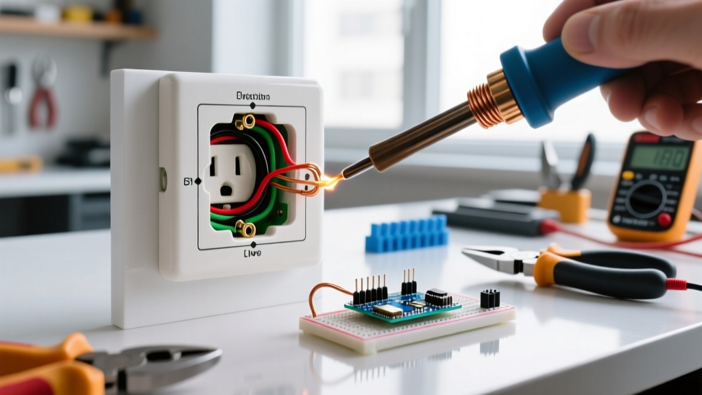

Why Did Your Outlet Fail? The Diagnostic Mindset
Before you grab a screwdriver to replace a dead or sparking wall plug, you must ask: why did it fail in the first place? Learning how to change out an electrical outlet is only half the battle; diagnosing the root cause ensures the new receptacle won’t suffer the exact same fate. In 2026, with continuous residential loads increasing due to high-draw electronics and smart home hubs, outdated wiring practices like backstabbing are failing at unprecedented rates.
A diagnostic approach prevents you from simply masking a severe fire hazard. According to the U.S. Consumer Product Safety Commission (CPSC), electrical receptacles are involved in thousands of residential fires annually, often stemming from loose connections and thermal degradation rather than the receptacle itself simply 'wearing out'.
Common Receptacle Failure Modes (And How to Spot Them)
When troubleshooting a faulty outlet, visually inspect the device and the wiring upon removal. Here are the most frequent failure modes encountered in residential wiring:
| Failure Mode | Visual Symptom | Root Cause | The Fix |
|---|---|---|---|
| Push-In (Backstab) Failure | Melted plastic around the rear wire holes; intermittent power. | Spring-loaded internal contacts lose tension over time, creating high resistance and heat under load. | Always use side-terminal screw wiring or back-wire clamps on the new device. |
| Thermal Degradation | Brown or black scorch marks on the brass/nickel screws or yoke. | Loose terminal screws causing micro-arcing and extreme localized heat. | Strip wire back to clean copper; torque terminal screws to 14 in-lbs. |
| Shared Neutral (MWBC) Fault | Outlet works, but turning off one breaker leaves the adjacent hot wire live. | Multi-Wire Branch Circuit improperly wired or missing handle-tie. | Install a 2-pole handle-tie or replace with a double-pole breaker to kill all phases. |
| Open Ground / False Ground | Tester shows 'Open Ground', but a bootleg jumper wire exists between neutral and ground. | Previous DIYer faked a ground path to pass inspection or use 3-prong plugs. | Remove jumper; replace with GFCI receptacle labeled 'No Equipment Ground' per NEC 406.4(D). |
Pre-Replacement Safety: Beyond the Breaker Switch
The most critical step in changing out an electrical outlet is verifying the absence of voltage. Never rely solely on a non-contact voltage tester (NCVT), as phantom voltages or shielded cables can yield false negatives.
Expert Warning: If the outlet you are replacing is part of a Multi-Wire Branch Circuit (MWBC)—identifiable by a red and black hot wire connected to the same yoke—flipping a single breaker will only de-energize half the circuit. You must turn off both adjacent breakers in the panel to avoid a lethal 240V shock across the neutral bus.
Use a digital multimeter (such as the Fluke 117) or a dedicated plug-in circuit analyzer (like the Gardner Bender GFI-3501) to test from Hot-to-Neutral, Hot-to-Ground, and Neutral-to-Ground before touching a single terminal screw.
Step-by-Step: How to Change Out an Electrical Outlet Safely
Once the circuit is verified dead, follow this precise workflow to ensure a code-compliant, long-lasting installation.
1. Extract and Inspect the Wiring
Unscrew the yoke and gently pull the receptacle from the junction box. Inspect the wire insulation. If the thermoplastic insulation is brittle, cracked, or shows heat damage extending more than an inch into the box, you must cut the damaged portion back. The National Electrical Code (NEC) requires conductors to be free from physical damage and extend at least 3 inches past the face of the box.
2. Prep the Conductors
Using precision wire strippers (e.g., Klein Tools 11063W), strip exactly 3/4-inch of insulation from the solid copper conductors. Do not score or nick the copper wire itself, as nicks create mechanical weak points that can snap under the torque of the terminal screw.
3. Terminate Using the Side-Wire Method
Wrap the bare copper wire clockwise around the terminal screw. The clockwise direction ensures that tightening the screw pulls the wire loop tighter, rather than pushing it out from under the screw head.
- Black (Hot) Wire: Connects to the brass screw.
- White (Neutral) Wire: Connects to the silver screw.
- Bare/Green (Ground) Wire: Connects to the green grounding screw.
Pro Tip: For commercial-grade installations, use a torque screwdriver set to 14 in-lbs to ensure the connection meets UL 498 pull-out test standards without crushing the copper.
Upgrading in 2026: GFCI, AFCI, and Tamper-Resistant Mandates
When replacing an outlet, you are legally required to bring the installation up to current local codes. The 2026 NEC updates have expanded the requirements for life-safety devices:
- Tamper-Resistant (TR) Mandate: All 15A and 20A, 125V and 250V non-locking receptacles in residential dwellings must be TR-rated. These feature internal shutters that prevent children from inserting single objects. Models like the Leviton T5325-W (approx. $3.50) are the baseline standard.
- GFCI Expansion: Ground Fault Circuit Interrupters are now required in all wet locations, kitchens, bathrooms, garages, and within 6 feet of sinks. If replacing a standard outlet near a kitchen island, you must upgrade to a 20A GFCI (e.g., Eaton GFTR20W, approx. $22.00).
- AFCI Protection: While AFCI is typically handled at the breaker panel, if your home features older feed-through AFCI receptacles, they must be replaced with like-for-like devices to maintain bedroom and living room arc-fault protection.
Post-Installation Verification
Once the outlet is secured in the box and the cover plate is installed, restore power at the breaker. Do not assume the job is finished until you verify the wiring topology. Plug in a 3-light receptacle tester. You are looking for two yellow lights (correct polarity). If the red light illuminates, you have a hot/ground reverse—a dangerous fault that requires immediate re-wiring.
For GFCI outlets, press the built-in 'TEST' button. The internal solenoid should trip within 25 milliseconds, cutting power to the face of the receptacle. The Electrical Safety Foundation International (ESFI) recommends testing all GFCI receptacles monthly to ensure the internal sensing circuitry hasn't degraded due to power surges.
Frequently Asked Questions
Can I replace a 15-amp outlet with a 20-amp outlet?
Only if the circuit wiring is 12 AWG copper and the breaker is rated for 20 amps. Installing a 20-amp receptacle on a 15-amp circuit with 14 AWG wire is a code violation, as it allows users to plug in high-draw appliances that could overheat the undersized wiring before the breaker trips. You can, however, install a 15-amp receptacle on a 20-amp circuit (provided it is a duplex receptacle).
Why does my new outlet spark when I plug something in?
A small, quick blue spark is normal when plugging in a device with a large capacitive load (like a laptop power supply or vacuum cleaner) while the device's internal switch is in the 'ON' position. However, a large orange spark accompanied by a popping sound or burning smell indicates a loose terminal connection or a failing appliance cord, requiring immediate troubleshooting.