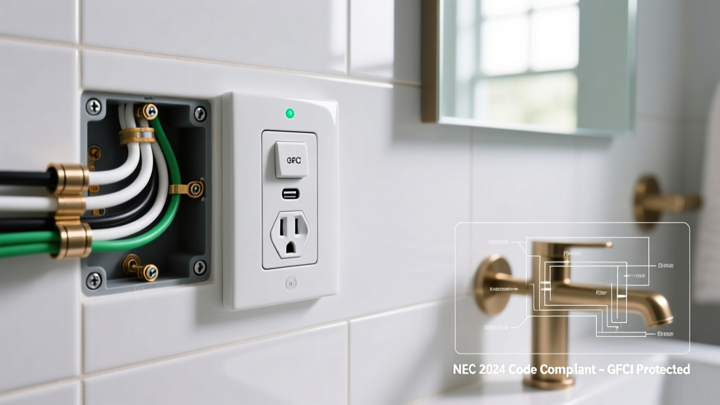

Bridging Design and Electrical Safety in the Bathroom
When homeowners and interior designers search for bathroom electrical outlet ideas, the focus is often on aesthetics: hidden placements, integrated vanity lighting, or sleek cover plates. However, as a wiring diagram reference hub, we must ground these design concepts in strict electrical engineering and safety codes. The modern bathroom is a high-moisture, high-load environment where hair dryers, heated mirrors, smart toilets, and electric toothbrushes compete for power on a single circuit.
In 2026, integrating modern conveniences like USB-C fast charging and smart home automation requires a deep understanding of load-side versus line-side wiring, box fill calculations, and Ground Fault Circuit Interrupter (GFCI) mandates. This guide translates popular bathroom outlet concepts into actionable wiring schematics and National Electrical Code (NEC) compliant layouts.
The Non-Negotiable Foundation: NEC Bathroom Circuit Mandates
Before exploring specific outlet ideas, every wiring diagram must adhere to the foundational rules set by the National Fire Protection Association (NFPA) regarding bathroom circuits. According to NEC Article 210.11(C)(3), every bathroom must have at least one dedicated 20-ampere branch circuit that supplies only bathroom receptacles.
Electrician’s Note: You cannot share the bathroom receptacle circuit with the bathroom lighting, exhaust fan, or outlets in other rooms. Furthermore, NEC Article 210.8(A)(1) mandates that all 125V, 15A, and 20A receptacles in the bathroom must have GFCI protection.
This means your baseline wiring diagram always starts at the breaker panel with a 20A single-pole GFCI or AFCI/GFCI dual-function breaker, feeding 12 AWG THHN/THWN-2 copper conductors to the first outlet box in the bathroom.
4 Practical Bathroom Electrical Outlet Ideas (With Wiring Schematics)
1. The Dual-Location GFCI Layout (Line vs. Load Wiring)
The Idea: Place a primary GFCI outlet near the main sink and a secondary, standard duplex outlet across the room (e.g., near a makeup vanity or bidet) to save on the cost of multiple GFCI devices.
Wiring Diagram Reference: This relies on the "LOAD" terminals of the primary GFCI.
- Power Source (Panel): 12/2 Romex enters Box 1. The bare copper grounds to the green screw. The white neutral connects to the silver LINE terminal. The black hot connects to the brass LINE terminal.
- Downstream Feed: A second 12/2 Romex exits Box 1 toward Box 2. The white neutral connects to the silver LOAD terminal. The black hot connects to the brass LOAD terminal.
- Box 2 (Standard Receptacle): The incoming 12/2 wires connect to the standard LINE terminals. Because it is fed from the LOAD side of Box 1, Box 2 is now GFCI protected.
Pro Tip: Use a torque screwdriver set to 14 in-lbs when tightening terminal screws on devices like the Eaton GFTR2-15W to prevent loose connections that cause arc faults.
2. Integrated USB-C Receptacles for Smart Vanities
The Idea: Install a USB-C/USB-A combination receptacle (like the Leviton T5636) at the vanity to charge electric toothbrushes, shavers, and smartphones without bulky adapters.
Wiring Diagram Reference: USB receptacles do not have built-in GFCI protection. Therefore, they must be wired downstream of a GFCI device or on a circuit protected by a GFCI breaker.
When wiring the Leviton T5636, you will notice it requires a deep electrical box. The internal transformer for the USB ports generates heat and takes up physical space. You must calculate box fill per NEC Article 314.16. The device counts as two conductors, plus the incoming and outgoing wires. A minimum 22.5 cubic-inch single-gang "deep" box is highly recommended to prevent crushing the 12 AWG wires against the back of the yoke, which can compromise the USB charging circuitry over time.
3. Recessed Outlet Boxes for Wall-Mounted Appliances
The Idea: Use a recessed outlet box (such as the Arlington Industries FB282 Flip Box) behind wall-mounted hair dryers, Dyson Airwrap storage docks, or smart mirrors to eliminate the ugly "plug bulge" and allow items to sit flush against the wall or inside a cabinet.
Wiring Diagram Reference: The FB282 is designed for retrofit or new construction and features a hinged cover. The wiring is identical to a standard receptacle, but the physical orientation changes. Because the receptacle is mounted horizontally or vertically inside a recessed cavity, you must use "back-wiring" (side-wiring with a pressure plate) rather than looping wires around the terminal screws. Back-wiring provides a more secure mechanical connection in tight, awkward recessed spaces where a screw-loop might get pinched when the device is pushed into the wall cavity.
4. Smart Receptacles for Automated Exhaust Fans and Heaters
The Idea: Install a Wi-Fi or Z-Wave smart receptacle (like the Leviton Decora Smart Wi-Fi Outlet) to control plug-in towel warmers, ambient space heaters, or auxiliary ventilation.
Wiring Diagram Reference: Smart receptacles require a constant power source to keep their internal Wi-Fi radios active. This means they require a dedicated Neutral (White) wire. In older homes (pre-1980s), switch boxes and some outlet boxes were wired using only a hot and a switched hot, with no neutral. In modern 2026 bathroom layouts, a 12/3 or 12/2 with ground is standard, ensuring the neutral is present. Wire the black hot to the smart outlet's LINE terminal, the white neutral to the silver terminal, and the ground to the green. If the smart outlet controls a downstream device, use the LOAD terminals to pass power through.
Wiring Matrix: Bathroom Outlet Configurations
The following matrix provides a quick-reference guide for electricians and advanced DIYers planning their bathroom rough-in.
| Outlet Concept | Recommended Device | Min. Box Volume | Wire Gauge | Breaker Size |
|---|---|---|---|---|
| Primary GFCI (Sink) | Eaton GFTR2-20W (Weather Resistant) | 22.5 cu. in. | 12 AWG | 20A AFCI/GFCI |
| USB-C Vanity Charging | Leviton T5636 (3.6A USB-C) | 22.5 cu. in. | 12 AWG | 20A (GFCI upstream) |
| Recessed Cabinet Outlet | Arlington FB282 + Standard Duplex | 18.0 cu. in. | 12 AWG | 20A (GFCI upstream) |
| Smart Towel Warmer Control | Leviton D215P (Decora Smart) | 24.0 cu. in. | 12 AWG | 20A (GFCI upstream) |
Step-by-Step: Wiring a Downstream USB-C Vanity Outlet
To solidify the wiring diagram reference, here is the exact sequence for wiring a USB-C outlet downstream from a main bathroom GFCI, ensuring Electrical Safety Foundation International (ESFI) compliance.
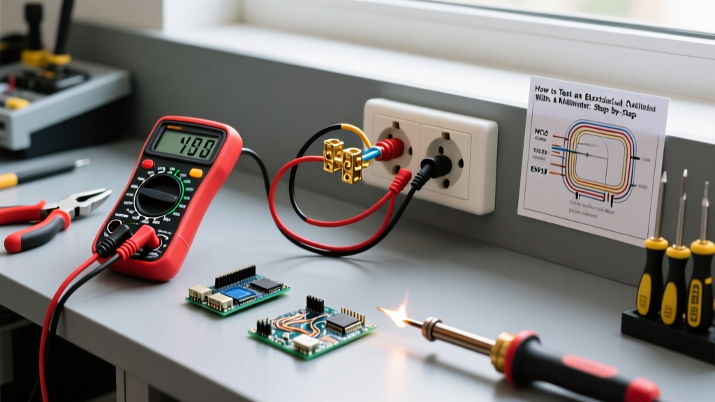
- Verify Power: Turn off the 20A bathroom breaker at the panel. Use a non-contact voltage tester and a multimeter to confirm 0V at both the GFCI and the downstream vanity box.
- Prepare the Wires: Strip exactly 3/4 inch of insulation from the 12 AWG black and white wires using wire strippers. Do not nick the copper, as this creates a failure point.
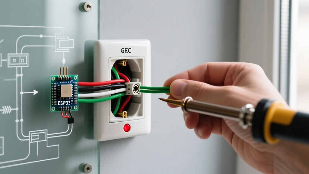
- Terminate the GFCI (Box 1): Connect the incoming panel wires to the LINE terminals. Connect the outgoing wires (heading to the vanity) to the LOAD terminals. Secure the ground wires together with a wire nut and a pigtail to the GFCI green screw.
- Terminate the USB Outlet (Box 2): Connect the incoming black wire to the brass LINE terminal on the USB receptacle. Connect the incoming white wire to the silver LINE terminal. Connect the ground to the green screw.
- Box Fill Check: Ensure no bare copper ground wire is touching the brass or silver terminal screws. Fold the wires neatly into the back of the deep box using a "Z" fold pattern to avoid pinching the internal USB transformer.
- Torque and Test: Tighten all terminal screws to the manufacturer's specified torque (usually 14 in-lbs). Restore power and test the GFCI "TEST" button to ensure it successfully cuts power to the downstream USB outlet.
Common Failure Modes & Troubleshooting
Even with perfect wiring diagrams, bathroom environments introduce unique edge cases that cause outlet failures.
Nuisance GFCI Tripping from High Humidity
The Problem: After a hot shower, the primary GFCI trips, cutting power to the vanity USB outlets and smart mirrors.
The Cause: Standard indoor GFCIs can accumulate microscopic condensation inside the sensor coil housing, creating a temporary leakage path to ground.
The Fix: Upgrade the primary sink outlet to a Weather-Resistant (WR) GFCI, identifiable by a "WR" stamp on the face. These feature UV-resistant and moisture-sealed internal components that prevent humidity-induced nuisance tripping.
Shared Neutral Tripping the Breaker
The Problem: The 20A AFCI/GFCI breaker trips immediately upon resetting, or trips when a hair dryer is turned on.
The Cause: An apprentice or DIYer accidentally mixed the neutral wire from the bathroom circuit with the neutral wire from the adjacent bedroom lighting circuit in the junction box. GFCI and AFCI devices monitor the exact balance of current between the hot and neutral. If the return current takes a different neutral path, the device detects a "ground fault" or "arc fault" and trips.
The Fix: Isolate the bathroom neutral. Ensure the white wire returning from the bathroom loads connects only to the bathroom's dedicated 20A circuit neutral bus or the GFCI LOAD neutral terminal.
Final Thoughts on Bathroom Outlet Infrastructure
The best bathroom electrical outlet ideas are those that remain invisible to the user while providing flawless, safe power. By treating your bathroom layout as a structured wiring diagram rather than just a cosmetic afterthought, you ensure that high-draw appliances and sensitive smart electronics operate safely for decades. Always prioritize deep junction boxes, strict adherence to NEC 20A dedicated circuit rules, and proper LINE/LOAD sequencing to future-proof your bathroom's electrical infrastructure.