
The Definitive Wiring Diagram Reference for the USA Electric Outlet
The landscape of residential and commercial power distribution is continuously evolving. As of 2026, with the widespread adoption of high-draw smart appliances, whole-home battery backups, and Level 2 electric vehicle (EV) chargers, understanding the standard USA electric outlet is no longer just about wiring a simple lamp. It requires strict adherence to the National Electrical Code (NEC), precise torque specifications, and a deep understanding of NEMA (National Electrical Manufacturers Association) configurations.
This comprehensive wiring diagram reference breaks down the anatomy, installation procedures, and code requirements for the most common 120V and 240V receptacles found in North America. Whether you are an apprentice electrician or an advanced DIYer, these guidelines will ensure your installations are safe, code-compliant, and built to last.
Anatomy of a Standard USA Electric Outlet
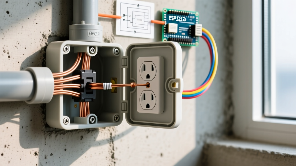
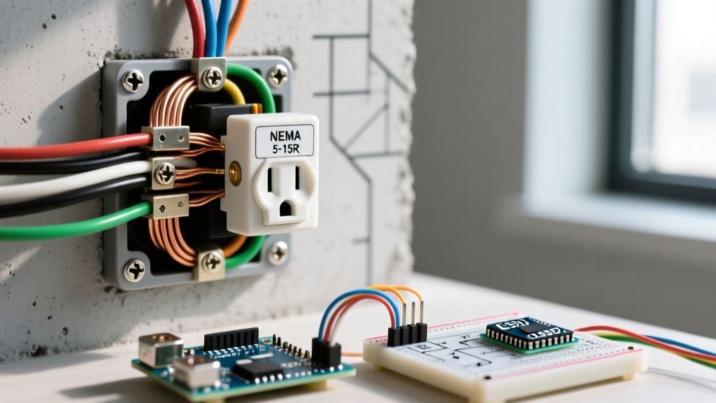
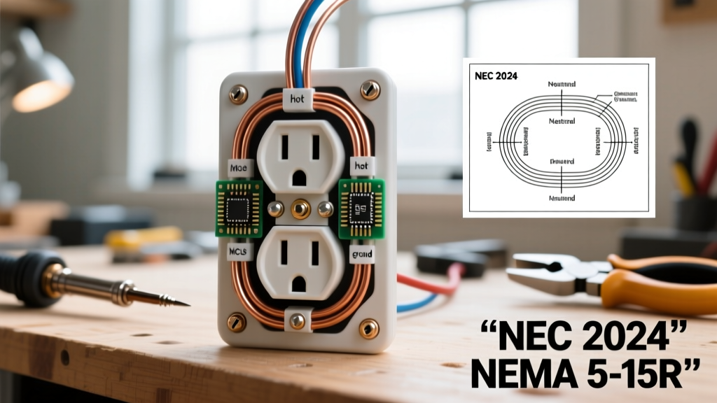
Before connecting any wires, you must understand the terminal layout and the corresponding NEC color codes for branch circuit wiring. A standard 120V duplex receptacle features three primary connection points:
- Hot Terminal (Brass Screw): Connects to the ungrounded conductor. In standard NM-B (Romex) cable, this is the black or red wire. It carries the 120V alternating current from the breaker panel.
- Neutral Terminal (Silver Screw): Connects to the grounded conductor. This is the white wire. It completes the circuit back to the panel's neutral bus bar.
- Ground Terminal (Green Screw): Connects to the equipment grounding conductor. This is the bare copper or green insulated wire. It provides a safe path for fault currents, tripping the breaker in the event of a short circuit.
NEMA Standard Configurations Matrix
The USA relies on NEMA standards to ensure plugs and receptacles match specific voltage and amperage ratings. Below is a reference matrix for the most common residential and light-commercial outlets.
| NEMA Code | Voltage | Amperage | Typical Application | Min. Copper Wire Gauge | Breaker Size |
|---|---|---|---|---|---|
| 5-15R | 125V | 15A | General Living Areas, Bedrooms | 14 AWG | 15A |
| 5-20R | 125V | 20A | Kitchens, Bathrooms, Garages | 12 AWG | 20A |
| 14-30R | 125/250V | 30A | Electric Clothes Dryers | 10 AWG | 30A |
| 14-50R | 125/250V | 50A | EV Chargers, Electric Ranges | 6 AWG | 50A |
Step-by-Step Wiring: Standard 120V (NEMA 5-15R & 5-20R)
When wiring a standard 15-amp or 20-amp USA electric outlet, precision is just as important as correctness. Follow this professional-grade procedure to ensure a secure, low-resistance connection.
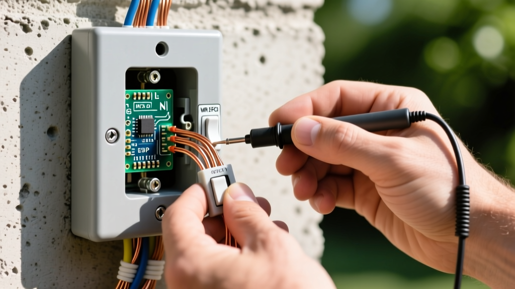
- De-energize and Verify: Turn off the circuit breaker. Use a non-contact voltage tester (NCVT) at the outlet, then verify with a digital multimeter between the hot and neutral slots to confirm 0V.
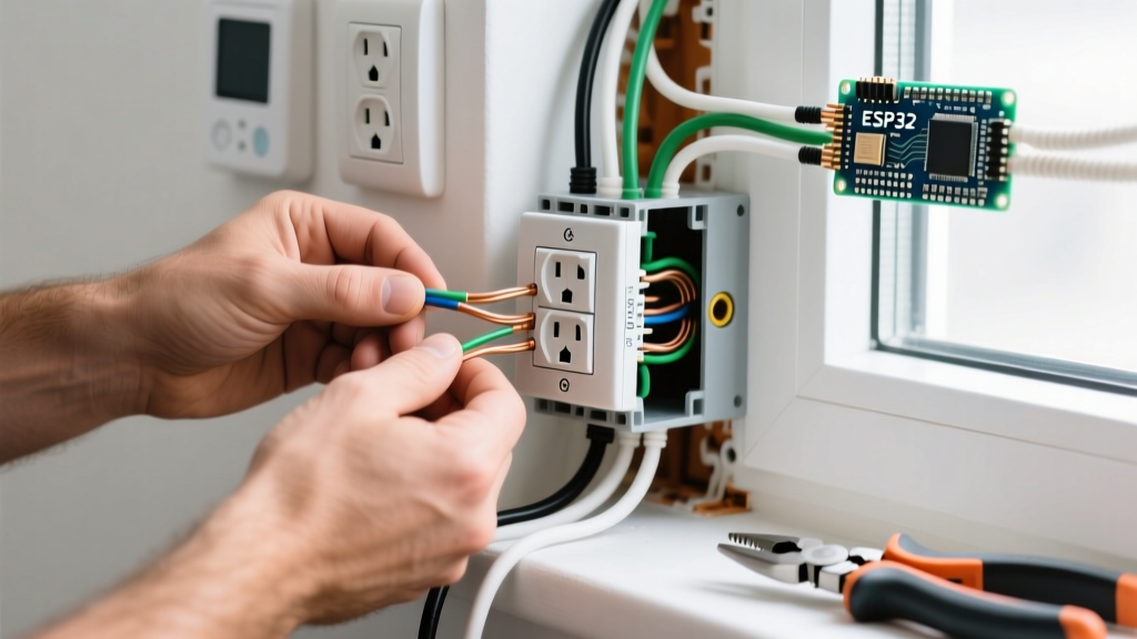
- Prepare the Conductors: Strip exactly 3/4 inch of insulation from the solid copper wires. Stripping too little leaves exposed copper outside the terminal; stripping too much exposes bare wire near the screw head, creating a shock hazard.
- Form the J-Hook: Use needle-nose pliers to bend the stripped wire into a tight 'J' or shepherd's hook shape.
- Clockwise Termination: Loop the wire around the terminal screw in a clockwise direction. This ensures that as you tighten the screw, the loop pulls tighter around the shaft rather than splaying outward.
- Apply Correct Torque: This is the most skipped step by amateurs. According to modern NEC 110.14(D) requirements, terminations must be torqued to the manufacturer's specifications. For most standard 15A/20A receptacles (like Leviton or Hubbell), this is typically 14 in-lbs. Use an insulated torque screwdriver to prevent under-tightening (which causes arcing and fires) or over-tightening (which strips the brass threads).
- Grounding Pigtails: If you are wiring multiple outlets in a single circuit run, NEC 250.148 requires you to use a wire nut and a pigtail to connect the ground wires. You cannot rely solely on the receptacle's grounding strap to pass the ground downstream, as removing the device would break the ground path for downstream outlets.
Pro-Tip: Avoid 'Backstabbing'
Never use the push-in 'backstab' terminals on the back of a 15A/20A receptacle. These rely on a small internal spring clip that makes minimal contact with the wire. Over time, thermal expansion and contraction from electrical loads cause these connections to loosen, leading to high resistance, melting, and electrical fires. Always use the side screw terminals or screw-clamp plate terminals.
Heavy-Duty 240V Wiring: NEMA 14-50R for EV Charging
The NEMA 14-50R is a 4-prong, 50-amp, 125/250V receptacle. In 2026, it is the gold standard for residential Level 2 EV charging and heavy electric ranges. Unlike a standard 120V outlet, this requires two hot legs, a neutral, and a dedicated equipment ground.
Wiring Specifications for 14-50R
- Conductor Size: 6 AWG copper (THHN in conduit or 6/3 NM-B Romex). Aluminum is not recommended for residential 14-50R due to higher resistance and termination oxidation risks.
- Conduit Fill: If using THHN wire, three or four 6 AWG wires require a minimum of 3/4-inch EMT or PVC conduit to manage heat dissipation.
- Terminal Torque: Heavy-duty receptacles require significantly higher torque. Hubbell and Bryant 14-50R receptacles typically require between 35 to 45 in-lbs of torque on the terminal screws. Always check the sticker on the back of the specific device.
- Neutral vs. Ground: The white wire connects to the silver neutral terminal (often marked 'W' or 'Neutral'). The bare/green wire connects to the green ground terminal (marked 'G'). Never bond neutral and ground at the receptacle. They must remain isolated downstream of the main service panel.
For comprehensive guidelines on installing home charging infrastructure, refer to the Department of Energy EV Charging Guidelines, which detail load calculations and circuit sizing for modern electric vehicles.
NEC Compliance: AFCI, GFCI, and Tamper-Resistant Rules
The National Electrical Code is updated every three years, and local jurisdictions adopt these standards to mitigate fire and shock hazards. When installing any USA electric outlet, you must adhere to the following protection mandates:
1. Tamper-Resistant (TR) Receptacles
Per NEC Article 406.12, all 15A and 20A, 125V and 250V non-locking receptacles installed in dwelling units must be Tamper-Resistant. TR outlets feature internal spring-loaded shutters that only open when equal pressure is applied to both the hot and neutral slots simultaneously, preventing children from inserting foreign objects. There are virtually no exceptions to this rule in modern residential construction.
2. Ground-Fault Circuit Interrupter (GFCI)
GFCI protection monitors the current imbalance between the hot and neutral conductors. If it detects a leakage as small as 4 to 6 milliamps, it trips the circuit in milliseconds. NEC Article 210.8 mandates GFCI protection for all 125V, 15A and 20A receptacles in:
- Bathrooms and Kitchens (countertop areas)
- Garages, accessory buildings, and crawl spaces
- Outdoors (including eaves and roofs)
- Laundry areas and within 6 feet of a wet bar sink
3. Arc-Fault Circuit Interrupter (AFCI)
AFCI breakers detect dangerous electrical arcs (sparking) that can ignite surrounding wood or insulation. NEC Article 210.12 requires combination-type AFCI protection for nearly all 120V branch circuits supplying outlets in living rooms, bedrooms, hallways, and closets.
For the most current code cycles and localized amendments, always consult the National Fire Protection Association NEC Resources.
Critical Failure Modes and Troubleshooting
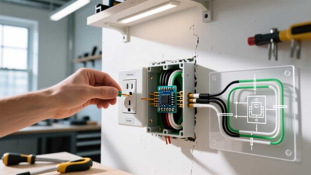
Even experienced installers can make mistakes that pass initial visual inspection but fail under load. Use a commercial-grade receptacle tester to check for these common wiring faults:
- Reverse Polarity: The hot and neutral wires are swapped. The outlet will power a device, but the device's internal switch will only interrupt the neutral path, leaving internal components energized and posing a severe shock hazard during maintenance.
- Open Ground: The ground wire is disconnected or broken. The outlet will function normally, but a fault in a plugged-in metal appliance will not trip the breaker, electrifying the appliance chassis.
- Bootleg Ground: A highly dangerous, illegal practice where a jumper wire is installed between the neutral silver screw and the green ground screw to trick a 3-prong tester. If the neutral wire ever breaks upstream, the metal casing of any plugged-in appliance will become energized with 120V. Never do this.
- Shared Neutral (Multi-Wire Branch Circuit Error): If two hot wires on different phases share a single neutral wire, and the breaker handles are not tied together, turning off one breaker while working on the outlet can result in the neutral carrying the return current from the live phase, causing a lethal shock.
Safety and Final Verification
Electrical work carries inherent risks of arc flash, electrocution, and property damage. Always practice strict Lockout/Tagout (LOTO) procedures at the main panel before beginning any work. The OSHA Electrical Safety Standards provide vital frameworks for hazard assessment and personal protective equipment (PPE) when working on or near energized systems.
Once your USA electric outlet is wired, torqued, and secured in the electrical box, restore power and test the receptacle using a calibrated digital multimeter. Measure Hot-to-Neutral (should read ~120V), Hot-to-Ground (~120V), and Neutral-to-Ground (should read less than 2V). Proper documentation and adherence to these diagram references will ensure a safe, reliable electrical infrastructure for decades to come.