
The Gap Between Schematics and Real-World Junction Boxes
When you search for a wiring diagram for electrical outlet installations, you are typically presented with a pristine, color-coded schematic. These diagrams assume ideal conditions: perfectly stripped 12 AWG or 14 AWG solid copper wires, clear line-of-sight routing, and strict adherence to the National Electrical Code (NEC). However, as any seasoned electrician knows, troubleshooting a faulty receptacle in a 40-year-old home rarely matches the textbook diagram. Real-world diagnostics require you to understand not just how the circuit should be wired, but how it fails when human error, thermal expansion, or outdated code practices interfere.
In this guide, we will deconstruct the standard 120V receptacle wiring diagram through the lens of advanced troubleshooting. We will identify the specific physical faults that cause circuits to trip, arc, or drop voltage, and provide a diagnostic matrix to help you map real-world symptoms back to the schematic.
The Baseline: Decoding the Standard 120V Receptacle Diagram
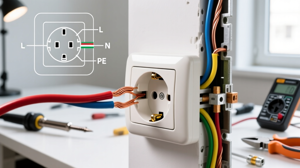
Before diagnosing deviations, you must internalize the baseline schematic for a standard 15A or 20A, 120V duplex receptacle (such as the ubiquitous Leviton 5320-W). The fundamental wiring diagram for an electrical outlet dictates three primary termination points:
- Hot (Line): Black (or red) insulation, terminated to the brass-colored screw.
- Neutral (Grounded Conductor): White (or gray) insulation, terminated to the silver-colored screw.
- Equipment Grounding Conductor (EGC): Bare copper or green insulation, terminated to the green grounding screw.
Under current NEC guidelines (specifically Article 406 regarding receptacle requirements), these connections must be secure, with no exposed copper outside the terminal housing, and must utilize tamper-resistant (TR) mechanisms in all dwelling unit habitable spaces. When a circuit fails, the fault almost always lies in a deviation from this baseline diagram.
Top 5 Real-World Wiring Faults Not Shown on Diagrams
Standard diagrams do not illustrate failure modes. Here are the most common physical faults you will encounter when troubleshooting an outlet circuit, along with how to diagnose them.
1. Push-In (Backstab) Connection Failures
Many modern receptacles feature spring-loaded push-in terminals on the back. While a basic wiring diagram might show these as a valid termination option, they are a leading cause of intermittent power loss and thermal failures. These terminals are only rated for 14 AWG solid copper wire. If an installer forces 12 AWG wire (required for 20A circuits) into a backstab, or if the wire is stranded, the spring tension fails over time due to thermal expansion and contraction.
Diagnostic Tip: If an outlet shows voltage on a non-contact tester but fails to power a load (like a hairdryer or vacuum), the backstab connection has likely arced and created a high-resistance fault. Remove the receptacle and inspect the back wire holes for melted plastic or black soot.
2. The "Bootleg" Ground (False Grounding)
In older homes with ungrounded (2-prong) wiring, DIYers sometimes install a 3-prong receptacle and place a jumper wire between the silver (neutral) screw and the green (ground) screw to trick a standard plug tester into reading "Correct." This is a severe shock hazard. If the neutral wire ever breaks upstream, the metal casing of any plugged-in appliance will become energized at 120V.
How to Diagnose: A standard 3-light receptacle tester (like the Klein Tools RT210, approx. $25) will read "Correct" on a bootleg ground. To expose the fault, use a ground impedance tester or simply remove the receptacle from the box to visually inspect for a jumper wire bridging the neutral and ground terminals.
3. Multi-Wire Branch Circuit (MWBC) Shared Neutral Errors
An MWBC uses two hot wires (typically black and red) sharing a single white neutral wire, connected to opposite phases of the electrical panel to cancel out the neutral current. If an electrician replaces an outlet and accidentally lands both the black and red hots on the same phase, or fails to use a handle tie, the shared neutral can be overloaded, leading to a melted neutral busbar or a fire.
How to Diagnose: Turn off the breaker for the black wire. If the red wire's circuit also loses power, they are likely on the same breaker or improperly handle-tied. Use a Fluke T6-1000 ($250) to measure the voltage between the black and red hot wires at the receptacle. If you read ~240V, they are on opposite phases (correct). If you read 0V, they are on the same phase (dangerous).
4. GFCI LINE vs. LOAD Reversal
When installing a Ground Fault Circuit Interrupter (GFCI) receptacle (e.g., Leviton T5320-W), the wiring diagram clearly distinguishes between LINE (power from the panel) and LOAD (power passing to downstream outlets). If reversed, the GFCI will power its own receptacles but will provide zero ground-fault protection to downstream devices, rendering the safety feature useless.
How to Diagnose: Press the "TEST" button on the GFCI. If the GFCI resets but downstream outlets on the same circuit remain dead, or if downstream outlets stay powered when the GFCI is tripped, the LINE and LOAD wires are reversed.
5. Reversed Polarity
This occurs when the hot (black) wire is landed on the silver (neutral) screw, and the neutral (white) wire is landed on the brass (hot) screw. The outlet will still power a lamp, but the internal switch of the appliance will break the neutral path rather than the hot path, leaving the appliance's internal components energized even when turned off.
Diagnostic Matrix: Symptom vs. Wiring Diagram Deviation
Use this matrix to cross-reference your physical symptoms with potential deviations from the standard wiring diagram for an electrical outlet.
| Observed Symptom | Probable Diagram Deviation | Diagnostic Tool Required | Corrective Action |
|---|---|---|---|
| Outlet works, but downstream outlets are dead. | Broken pigtail or failed backstab feed-through. | Non-contact voltage tester, Multimeter. | Replace backstabs with screw terminals and wire nuts/pigtails. |
| Breaker trips instantly upon plugging in a load. | Hot-to-ground short or damaged insulation in the box. | Fluke Multimeter (Continuity test). | Inspect for pinched wires behind the receptacle yoke. |
| GFCI trips randomly without a fault. | Neutral sharing with another circuit downstream. | Clamp meter on neutral wire. | Separate neutrals; ensure LOAD neutral only serves its specific hot. |
| Visible arcing or buzzing sound from the wall. | Loose terminal screw or 12 AWG wire in a 14 AWG backstab. | Visual inspection, Thermal camera. | Terminate using side-clamp or screw terminals torqued to spec. |
| Tester reads "Open Ground" in a metal box. | Missing equipment bonding jumper from box to receptacle. | Visual inspection, Multimeter. | Install a green grounding pigtail from the metal box to the green screw. |
Step-by-Step Troubleshooting Workflow
When an outlet fails, do not immediately start unscrewing terminals. Follow this systematic workflow to ensure safety and accurate diagnosis.
Step 1: De-Energize and Verify (The Zero-Energy State)
Locate the correct breaker and switch it to the OFF position. The OSHA electrical safety standards mandate verifying the absence of voltage before touching any conductor. Use a Category III or IV rated voltmeter to test between Hot-Neutral, Hot-Ground, and Neutral-Ground. All readings must be 0V.
Step 2: Map the Physical Wires to the Schematic
Pull the receptacle out of the junction box. Count the cables entering the box. If you see two cables (two blacks, two whites, two bare wires), this is a standard feed-through configuration. The diagram dictates that both blacks should be pigtailed to the brass screw, both whites to the silver, and both grounds to the green. If you see three cables, you are likely dealing with a switch loop or a complex daisy-chain that requires careful mapping.
Step 3: Inspect for Thermal Damage and Torque Issues
Examine the insulation on the wires. If the white neutral wire has blackened or melted insulation, this indicates a high-resistance connection generating excessive heat. According to the NFPA 70 (National Electrical Code), terminals must be tightened to the manufacturer's specified torque. While most residential DIYers do not use torque screwdrivers, ensuring the screw is firmly seated without stripping the brass threads is critical for preventing arc faults.
Advanced Diagnostics: Understanding Downstream Protection
A modern wiring diagram for an electrical outlet often includes upstream or downstream protection devices, such as Arc Fault Circuit Interrupters (AFCIs) or GFCIs. If your outlet is dead, but the breaker is not tripped, check the main panel for an AFCI breaker (identifiable by a purple or blue TEST button). AFCIs are highly sensitive to series arcing, which can be caused by a loose wire nut in a junction box anywhere on the circuit, not just at the outlet you are troubleshooting.
Furthermore, the Consumer Product Safety Commission (CPSC) heavily emphasizes the life-saving role of GFCIs in wet areas. If you are troubleshooting a kitchen or bathroom outlet that refuses to reset, remember that a GFCI receptacle will permanently lock out (fail safe) if its internal surge protection components have been compromised by a lightning strike or severe grid surge. In these cases, the wiring diagram remains correct, but the device itself must be replaced.
When to Call a Licensed Electrician
While understanding the wiring diagram for an electrical outlet empowers you to handle basic replacements and diagnostics, certain scenarios require professional intervention. If you discover aluminum wiring (identifiable by its dull gray color and "AL" stamping on the cable jacket), do not attempt to terminate it to a standard copper-rated receptacle. Aluminum requires CO/ALR rated devices and specific anti-oxidant paste. Additionally, if your diagnostic matrix points to a shared neutral MWBC issue in your main panel, the risk of fatal shock or arc flash necessitates a licensed professional. Always prioritize code compliance and personal safety over DIY expediency.