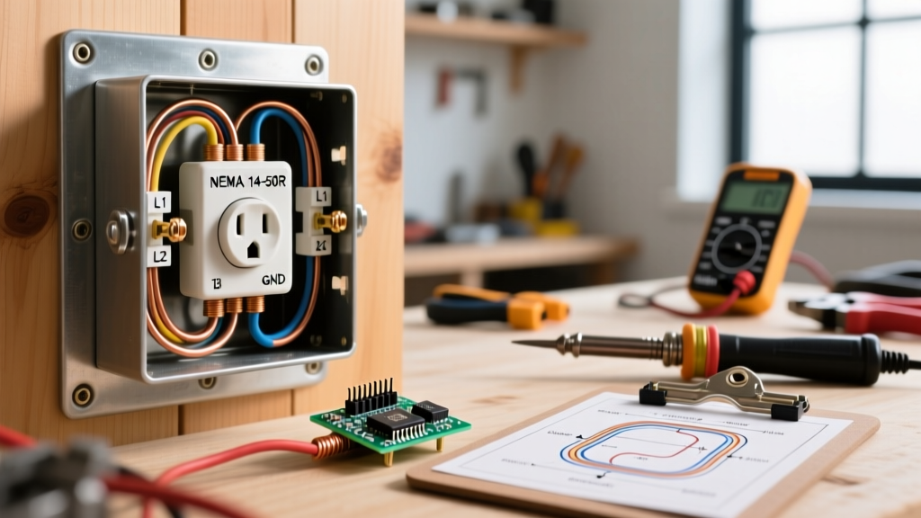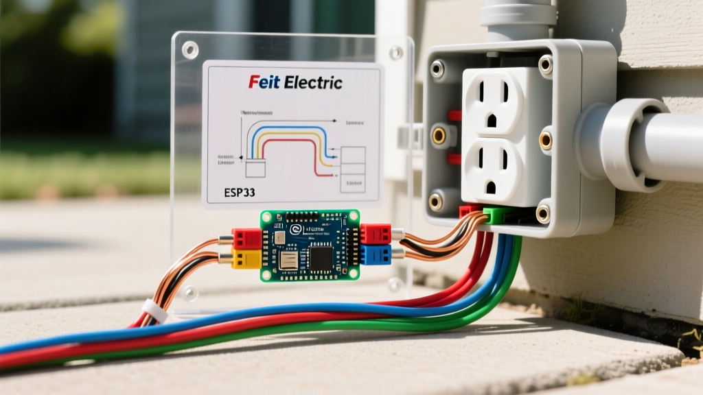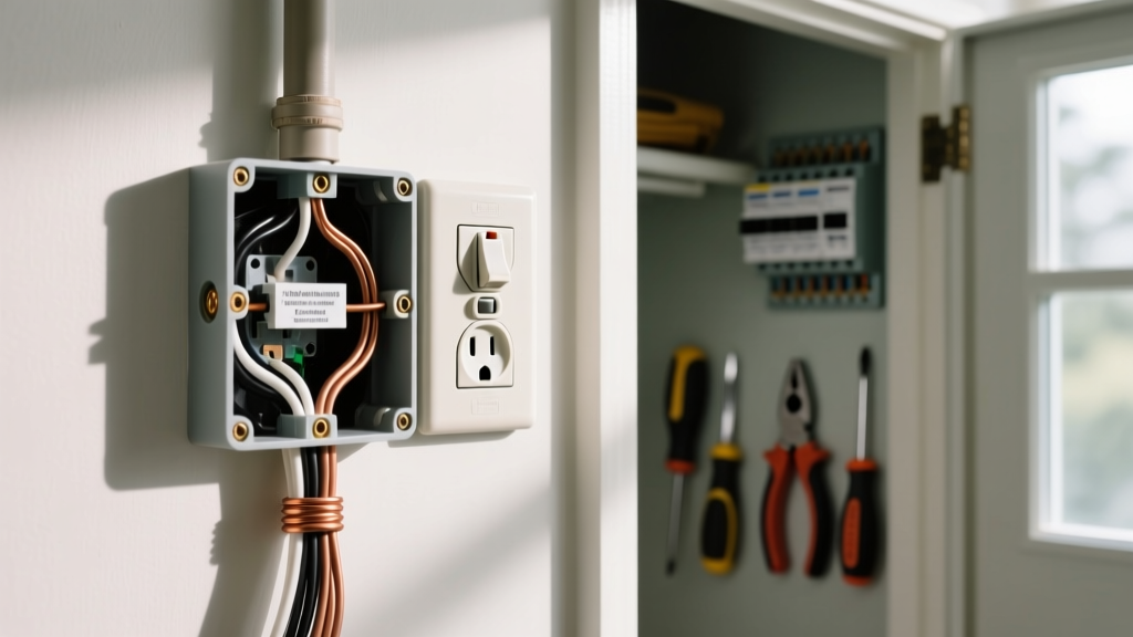

The Anatomy of an Electric Wall Outlet Problem
When a receptacle fails, sparks, or simply refuses to deliver power, guessing the root cause is not just inefficient—it is highly dangerous. Every complex electric wall outlet problem can be traced back to a deviation from standard wiring diagrams. Whether you are dealing with a simple open neutral, a miswired Multi-Wire Branch Circuit (MWBC), or a GFCI line-load reversal, understanding the schematic roadmap is the only way to ensure a safe, code-compliant repair.
In this 2026 wiring diagram reference guide, we bypass generic troubleshooting advice and dive deep into the exact schematic faults, National Electrical Code (NEC) requirements, and terminal-level diagnostics required to resolve modern receptacle failures.
Critical Safety Protocols Before Tracing Diagrams
Before opening any junction box or receptacle yoke, you must establish a zero-energy state. The National Fire Protection Association (NFPA) emphasizes that electrical fires cause hundreds of fatalities annually, many stemming from improper DIY troubleshooting on live circuits.
- Lockout/Tagout (LOTO): Switch off the corresponding circuit breaker and secure the panel. Never rely solely on a wall switch to de-energize an outlet.
- Verify with a True-RMS Multimeter: Use a CAT III or CAT IV rated meter (like the Fluke 117, approx. $190) to test Hot-to-Neutral, Hot-to-Ground, and Neutral-to-Ground. All readings must be 0.0V.
- NEC 110.14(D) Compliance: When re-terminating wires, modern code requires the use of a calibrated torque screwdriver. Standard 15A and 20A receptacles typically require 12 to 14 in-lbs of torque to prevent thermal creep and subsequent arcing.
Diagnostic Matrix: Mapping Symptoms to Wiring Faults
Use this reference table to cross-reference your physical symptoms with the underlying wiring diagram anomaly.
| Physical Symptom | Probable Wiring Fault | Diagram Check Point | NEC Reference |
|---|---|---|---|
| Outlet dead, but breaker is ON | Open Hot or Open Neutral upstream | Check push-in (backstab) connections on previous daisy-chained receptacle | NEC 110.14(B) |
| Devices work, but tester shows "Open Ground" | Missing equipment grounding conductor (EGC) or loose green screw | Verify bare copper/green wire is bonded to the metal box and green terminal | NEC 250.148 |
| Breaker trips immediately upon plugging in a load | Hot-Neutral short or MWBC neutral overload | Inspect for pinched wire insulation behind the yoke or shared neutral errors | NEC 210.4 |
| GFCI trips instantly or won't reset | Line and Load terminals reversed | Verify incoming power is on LINE terminals, not LOAD | NEC 406.4(D) |
Fault 1: The "Dead" Receptacle and Open Neutral Failures
The most frequent electric wall outlet problem in homes built between 1970 and 2010 is the failure of "backstabbed" push-in connectors. Standard wiring diagrams show wires wrapping clockwise around the brass (hot) and silver (neutral) terminal screws. However, builders often used the quick-wire push-in holes on the back of the yoke to save time.
Why Backstabbed Connections Fail
Push-in connectors rely on a small internal spring-metal tang to grip the 14 AWG or 12 AWG solid copper wire. Over years of thermal expansion and contraction (heating up when a 1500W space heater is used, cooling down when unplugged), this tang loses tension. The result is an open neutral. The hot wire still delivers 120V to the brass screw, but the neutral return path is broken. A plug-in tester will read "Open Neutral," and no current will flow.
Expert Fix: Never reuse push-in connectors. When replacing a failed receptacle, strip 3/4-inch of insulation and use the side-wiring screw terminals. For 12 AWG wire on a 20A circuit (like a Leviton 5262-C commercial grade receptacle, ~$7.50), you must use the screw terminal or a properly torqued back-wire clamp plate. Never wrap 12 AWG wire around a 15A receptacle screw terminal.
Fault 2: Multi-Wire Branch Circuit (MWBC) Neutral Overloads
An MWBC is an advanced wiring configuration where two hot wires (typically black and red) share a single neutral (white) wire, fed from a 240V double-pole breaker. On a wiring diagram, the two hot legs are 180 degrees out of phase. This means the shared neutral only carries the difference in current between the two legs, not the sum.
The DIY Receptacle Replacement Hazard
A massive safety hazard occurs when a homeowner replaces an outlet on an MWBC and breaks off the metal fin (break-off tab) on the neutral side, or fails to break it on the hot side.
- If you break the neutral tab but leave the hot tab intact: You have essentially paralleled the neutral paths, which can cause circulating currents and overheating.
- If you break the hot tab but leave the neutral tab intact (and the two hots are on the same phase): The shared neutral will carry the combined amperage of both circuits (e.g., 15A + 15A = 30A). Because the neutral wire is only rated for 15A or 20A, it will overheat and potentially cause a fire inside the wall cavity without ever tripping the breaker.
Diagram Rule: Under NEC 210.4, MWBCs require a simultaneous disconnecting means (a handle tie or a 2-pole breaker) to ensure both hot legs are de-energized when working on the shared neutral.
Fault 3: GFCI Receptacles and the Line vs. Load Conundrum
Ground Fault Circuit Interrupter (GFCI) receptacles are mandated by the NEC in all wet or damp locations (kitchens, bathrooms, garages, exteriors). A classic electric wall outlet problem arises when a GFCI is wired backward.
Reading the GFCI Schematic
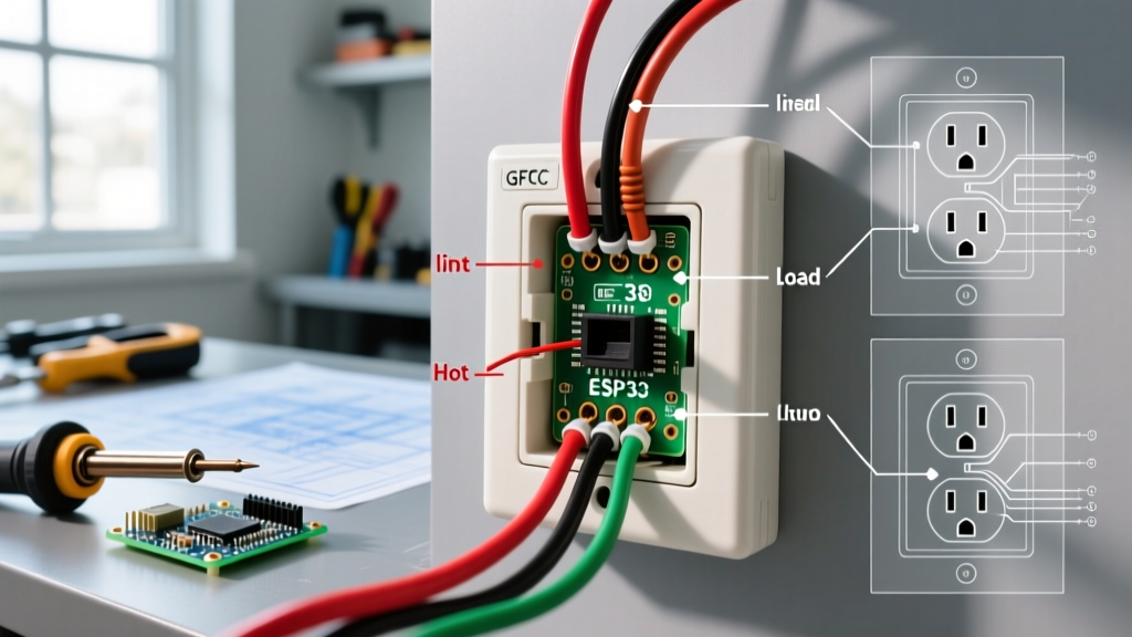
A GFCI receptacle has two distinct sets of terminals: LINE and LOAD.
- LINE: This is where the incoming power from the breaker panel connects. The internal sensing coil monitors the current differential between the hot and neutral on these terminals.
- LOAD: These terminals feed downstream standard receptacles, extending ground-fault protection to other outlets in the room.
If you connect the incoming power to the LOAD terminals, the GFCI will still power devices plugged directly into it. However, the internal monitoring circuit is bypassed. The "TEST" button will not trip the receptacle, and downstream outlets will have no GFCI protection. Always use a non-contact voltage tester to identify the incoming hot wire before connecting it to the LINE terminals.
Essential Diagnostic Tools for 2026
To accurately map physical wiring to schematic diagrams, you need precise instrumentation. Skip the $8 plug-in cube testers for complex diagnostics; they cannot detect high-resistance connections or bootleg grounds.
- Klein Tools RT250 Digital Voltage Tester ($45 - $55): Features a built-in solenoid load to trip GFCIs and accurately detects reversed hot/neutral conditions without relying on a ground reference.
- Ideal SureTest Circuit Analyzers ($120 - $160): Measures actual voltage drop under load and verifies the exact impedance of the equipment grounding conductor, crucial for ensuring breakers will trip during a fault.
- Klein Tools 32500 Torque Screwdriver ($80 - $100): Essential for meeting NEC 110.14(D) termination torque specifications, preventing the thermal loosening that causes 40% of all receptacle fires.
Frequently Asked Questions
Why does my outlet have power according to my meter, but devices won't turn on?
This is the hallmark of an "open neutral" or a "high-resistance neutral" fault. Your multimeter is drawing micro-amps to read 120V between the hot and neutral slots. However, when you plug in a lamp (which draws amps), the high-resistance connection (often a failing backstab connector upstream) collapses under the load, dropping the voltage to near zero. You must trace the wiring diagram backward to the previous outlet in the daisy chain and repair the neutral termination.
Can I replace a standard 15A receptacle with a 20A receptacle to stop it from tripping?
No. The amperage rating of the receptacle must match the wire gauge and the breaker size. If your circuit uses 14 AWG wire and a 15A breaker, installing a 20A receptacle (which accepts a 20A plug with a sideways neutral blade) is a code violation. Furthermore, the breaker trips because the total load exceeds 15 amps; changing the receptacle does not change the circuit's capacity and creates a severe fire hazard. Always refer to NEC Table 210.21(B)(3) for receptacle ratings.
What is a "bootleg ground" and how do I fix it?
A bootleg ground is an illegal and dangerous wiring hack where a jumper wire is connected between the neutral silver screw and the green ground screw on a 2-prong ungrounded outlet to trick a plug-in tester into reading "correct." If a hot wire faults to the metal chassis of an appliance, the chassis becomes energized at 120V, posing a lethal shock hazard. The Consumer Product Safety Commission (CPSC) strongly warns against this. The proper NEC 406.4(D) solution is to either run a new equipment grounding conductor back to the panel, or replace the receptacle with a GFCI and label it "No Equipment Ground."