
Understanding the Type E Electrical Outlet Standard
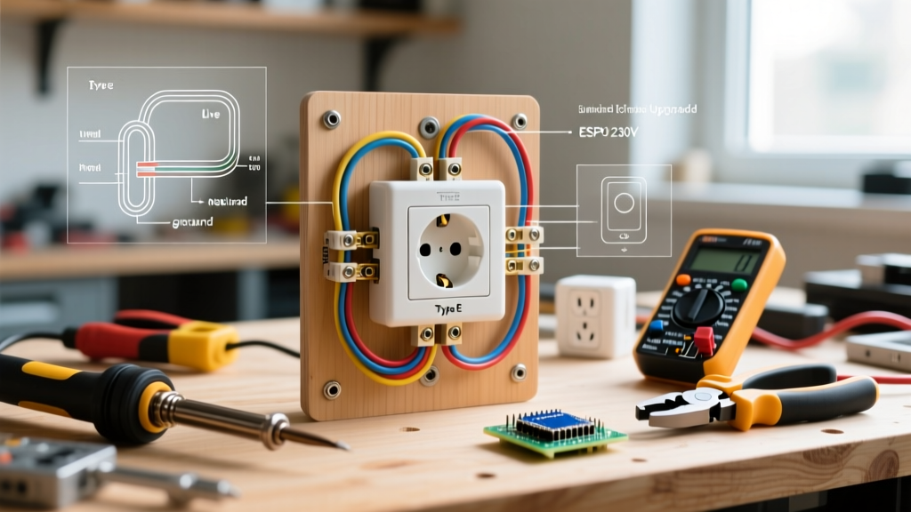
The Type E electrical outlet is a distinct 230V/50Hz receptacle standard predominantly deployed across France, Belgium, Poland, Slovakia, Czechia, and several African and Asian nations. Unlike the more ubiquitous Type F (Schuko) socket, which utilizes side-mounted earth clips, the Type E standard features a protruding male earth pin integrated directly into the socket face. This design choice fundamentally alters how electricians approach grounding verification, physical alignment, and retrofit scenarios in the field.
As of 2026, modernizing aging electrical infrastructure in Type E regions requires strict adherence to updated safety codes, such as the French NF C 15-100 standard, which mandates rigorous earth-loop impedance limits and specific circuit-breaker pairings. Whether you are upgrading a legacy ungrounded receptacle or integrating high-draw smart home appliances, understanding the physical and electrical nuances of the Type E system is critical for preventing thermal degradation and shock hazards.
⚠️ High-Voltage Safety Warning: Type E systems operate at 230V nominal (often peaking at 240V). Lethal current levels can be reached in milliseconds. Always isolate the circuit at the main distribution board and verify zero-energy state with a CAT III or CAT IV multimeter before exposing any terminal connections.
Anatomy and Physical Specifications
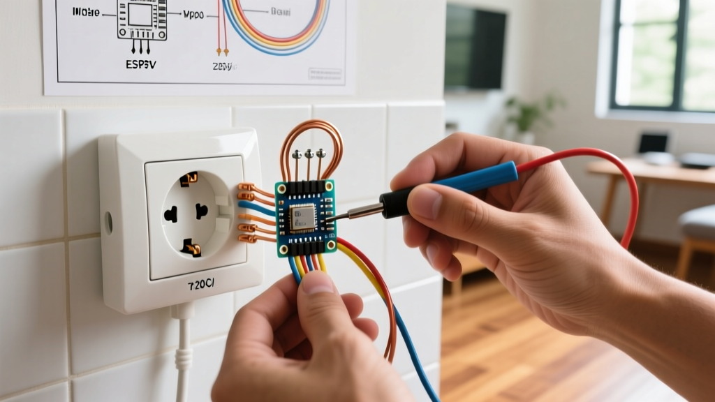
According to the IEC World Plugs guide, the Type E plug and socket interface relies on two 4.8mm round pins spaced exactly 19mm apart for the phase and neutral conductors. The defining feature is the 14mm long, 4.8mm diameter male earth pin located at the top of the socket, forming a triangular alignment. This physical geometry means that Type E plugs are polarized by physical design in some older appliances, though modern wiring conventions treat the phase and neutral as interchangeable in standard single-phase residential branching.
Core Wiring Scenarios for Type E Receptacles
Field conditions rarely match textbook diagrams. Below are the most common real-world scenarios electrical professionals and advanced DIYers encounter when working with Type E outlets.
Scenario 1: Upgrading Legacy 2-Pin to Grounded Type E
In many pre-1990s residential builds across Belgium and France, you will encounter ungrounded 2-pin sockets or early Type E sockets where the earth pin is present but entirely disconnected (a 'floating earth'). Swapping the faceplate to a modern grounded Type E receptacle without establishing a true earth path is a severe code violation and a life-safety hazard.
- The Hazard: If a phase-to-chassis fault occurs in a connected appliance, the metal casing becomes energized at 230V. Because the earth pin is physically protruding, a user might assume the system is grounded and touch the appliance while grounded, resulting in fatal electrocution.
- The Solution: You must pull a new 2.5mm² green/yellow earth conductor from the nearest distribution board earth bar or a verified local equipotential bonding point. Never daisy-chain the earth from a nearby water pipe, as modern PEX plumbing breaks electrical continuity.
Scenario 2: Smart Home and High-Draw Appliance Integration
The proliferation of smart home ecosystems has led to a surge in demand for connected Type E sockets. Models like the Legrand Netatmo or Schneider Electric Wiser smart Type E outlets (retailing between $75 and $95 USD in 2026) require specific wiring considerations.
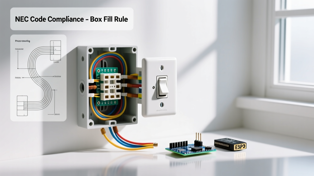
Unlike standard mechanical sockets, smart sockets contain internal relays and Wi-Fi/Zigbee radios that require a continuous neutral connection to power their logic boards. While standard Type E outlet boxes inherently contain a neutral wire, shallow masonry backboxes (often only 40mm deep) can cause severe wire crowding when adding the bulk of a smart socket's rear chassis. Upgrading to a 50mm or 60mm deep flush-mount backbox is highly recommended to prevent pinching the 2.5mm² conductors and to allow adequate heat dissipation for the internal relay.
Wire Sizing and Breaker Coordination (NF C 15-100 Framework)
Proper coordination between conductor cross-section, circuit breaker rating, and the maximum number of Type E outlets per circuit is non-negotiable. The table below outlines the standard residential requirements based on prevailing European and French codes.
| Conductor Size (Copper) | Max Breaker Rating | Max Outlets per Circuit | Typical Application |
|---|---|---|---|
| 1.5 mm² | 16A | 5 to 8 (depending on local code) | Lighting circuits (rarely used for outlets unless dedicated to low-draw) |
| 2.5 mm² | 20A | 12 | Standard Type E general-purpose outlet circuits |
| 4.0 mm² | 25A | Dedicated | Heavy single appliances (e.g., large water heaters) |
| 6.0 mm² | 32A | Dedicated | Induction hobs, EV charging adapters (hardwired preferred) |
Note: A standard Type E receptacle is physically rated for 16A continuous draw (approx. 3680W). Even if wired on a 20A breaker circuit, the individual socket must never be loaded beyond its 16A physical rating without utilizing specialized industrial-grade 20A/25A Type E variants.
Step-by-Step Installation: Modern Type E Socket Termination
For this procedure, we assume the installation of a standard 16A flush-mount Type E socket (e.g., Legrand Mosaic or Schneider Odace range) into a prepared 50mm deep backbox.
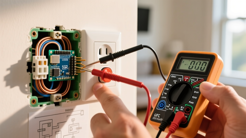
- Isolate and Verify: Turn off the MCB (Miniature Circuit Breaker) and lock it out. Use a CAT III multimeter to test Phase-to-Neutral, Phase-to-Earth, and Neutral-to-Earth to confirm 0V.
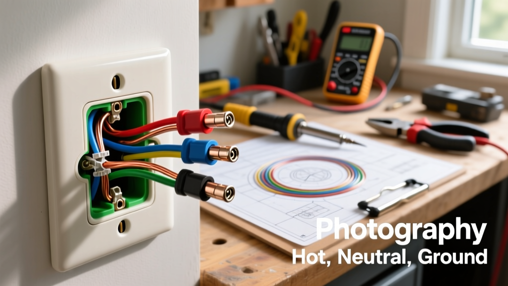
- Conductor Preparation: Strip exactly 12mm of insulation from the Brown (Phase), Blue (Neutral), and Green/Yellow (Earth) wires. Using a precision wire stripper like the Knipex MultiStrip 10 prevents nicking the copper strands, which reduces ampacity and creates hot spots.
- Earth First: Always terminate the earth wire first. Insert the 12mm bare copper into the top earth terminal. The earth wire should be left slightly longer (about 10-15mm of slack) than the phase and neutral wires. This ensures that if the cable is pulled, the earth connection is the last to disconnect.
- Phase and Neutral: Insert the Brown wire into the Phase terminal (typically marked 'L' or on the right side) and the Blue wire into the Neutral terminal (marked 'N' or on the left).
- Torque and Secure: Tighten the terminal screws to the manufacturer's specified torque, usually 0.8 Nm to 1.2 Nm for modern brass terminals. Undertightening causes arcing; overtightening shears the copper strands.
- Daisy-Chaining (if applicable): If feeding through to another outlet, use Wago 221 lever-nuts inside the backbox rather than looping two wires into a single terminal, which is prohibited by many modern codes and degrades the clamp pressure.
Critical Failure Modes and Troubleshooting
When troubleshooting existing Type E wiring, electricians frequently encounter specific edge cases that standard receptacle testers cannot identify.
1. The 'Floating Earth' Illusion
Standard plug-in neon testers often fail to accurately diagnose a floating earth in Type E sockets because the tester's internal impedance may not trigger a 30mA RCD (Residual Current Device) to trip, or it may capacitively couple to adjacent wiring, showing a 'green' light even when the earth pin has infinite resistance. Expert Fix: Always perform a dead-test earth continuity check using a low-resistance ohmmeter, or use a dedicated loop-impedance tester to measure the Ze and Zs values, ensuring they fall below the threshold required to trip the circuit's protective device within 0.4 seconds.
2. Reverse Polarity in Unpolarized Plugs
While Type E sockets accept plugs in only one orientation due to the earth pin, the socket itself is often wired with swapped phase and neutral by inexperienced installers. While many modern switch-mode power supplies do not care about polarity, single-pole switches on appliances (like desk lamps or older power tools) will only interrupt the neutral wire if polarity is reversed. This leaves the internal circuitry energized at 230V even when the appliance is switched 'off', presenting a severe shock hazard during maintenance or bulb changes.
3. Thermal Degradation at Terminal Clamps
High-draw appliances like portable air conditioners or space heaters drawing 14A-16A continuously will expose poor terminations. If the 12mm strip length was too short, the insulation enters the terminal clamp, causing a high-resistance connection. Over months of thermal cycling, this leads to melting of the socket faceplate. For a deep dive into thermal management in electrical enclosures, refer to the Schneider Electric FAQ and technical documentation regarding load balancing and heat dissipation in residential flush boxes.
Frequently Asked Questions (FAQ)
Can I use a Type F (Schuko) plug in a Type E electrical outlet?
No, not safely or reliably. A standard Type F plug lacks the female hole required to accept the protruding male earth pin of a Type E socket. While 'hybrid' CEE 7/7 plugs exist (which feature both the earth hole for Type E and side clips for Type F), attempting to force a pure Type F plug into a Type E socket will result in no earth connection and potential physical damage to the receptacle.
Is it legal to install a Type E socket in a bathroom?