
The 'Type C' Clarification: USB-C Receptacles vs. IEC Europlugs
Before breaking out the multimeter, we must address a common terminology collision in the electrical trade. In international wiring standards (IEC 60906), a 'Type C' outlet refers to the ungrounded, 2-pin 220-240V Europlug receptacle. However, in the North American DIY and electrical market, the search term type c electrical outlet almost universally refers to standard 120V NEMA 5-15R or 5-20R wall receptacles that feature integrated USB Type-C charging ports.
This inspection and testing guide focuses on the North American USB-C integrated receptacle (such as the Leviton T5636 or Top Greener TU2154A). These devices contain internal switching power supplies that step down 120V AC to 5V-20V DC, requiring a specialized testing approach that goes far beyond a standard $10 plug tester.
Expert Note: If you are actually troubleshooting an IEC Type C (European 220V) ungrounded outlet, standard US GFCI testers will not work. You must use a 220V-compatible European receptacle tester and verify the absence of a ground fault path, as Type C IEC relies on double-insulated appliances rather than a grounding conductor.
Essential Tools for USB-C Receptacle Inspection
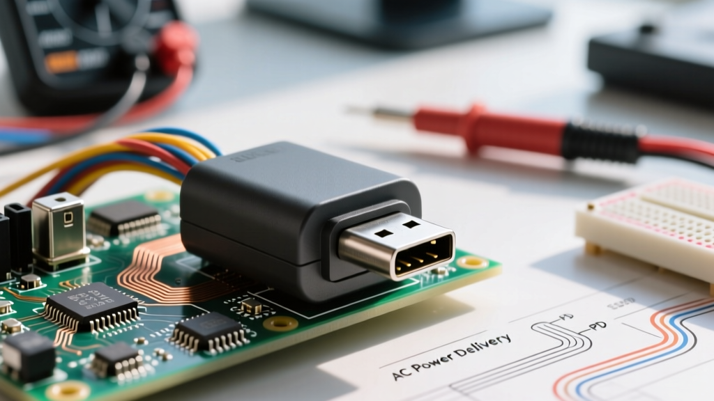
Testing the AC side of the outlet requires standard electrical tools, but verifying the DC Power Delivery (PD) negotiation requires specialized diagnostic equipment. As of 2026, with USB-C PD 3.1 becoming the baseline for modern electronics, ensuring your wall outlet is delivering the correct voltage profiles is critical.
- USB-C PD Tester / Multimeter: Devices like the MakerHawk USB-C Tester or FNIRSI FNB58 are mandatory. They read the PDO (Power Data Object) broadcast by the outlet's internal chip, verifying if it supports 5V, 9V, 12V, 15V, or 20V profiles.
- Advanced Receptacle Tester: The Klein Tools RT250 or similar GFCI/AFCI tester to verify the 120V AC wiring topology.
- Torque Screwdriver: Calibrated to 14-16 in-lbs for terminal screw verification.
- Thermal Imaging Camera: A smartphone attachment like the FLIR ONE to monitor heat dissipation from the internal AC-to-DC transformer.
Phase 1: AC Line Inspection and Box Fill Verification
The most common point of failure for a type c electrical outlet is not the USB circuitry itself, but the mechanical installation. USB-C receptacles are exceptionally deep—often protruding 1.5 to 1.75 inches into the wall cavity to accommodate the internal transformer and EMI shielding.
Verifying NEC Box Fill Calculations
According to guidelines published by the National Fire Protection Association (NFPA), standard 1-gang junction boxes (typically 14 to 18 cubic inches) are frequently undersized for modern USB-C receptacles. Overstuffing a box causes wire insulation damage and traps heat.
- Calculate the Device Volume: A standard receptacle counts as 2 wire allowances. However, because USB-C outlets contain internal clamps and transformers, many manufacturers require a minimum 22.5 cubic inch box (often a 'deep' 1-gang box or a 2-gang box with a 1-gang mud ring).
- Inspect Wire Bends: Ensure the 12 AWG or 14 AWG solid copper conductors are not kinked directly behind the USB transformer housing, which can short against the internal PCB if the insulation is compromised.
- Check Terminal Torque: Use a torque screwdriver set to 14 in-lbs on the side-wire terminal screws. Back-wire push-in connections are strictly prohibited for the high-draw internal transformers of 30W+ USB-C outlets.
AC Topology Testing
Plug in your advanced receptacle tester. Verify correct hot/neutral polarity and proper grounding. Because the USB-C circuitry relies on the neutral return path to complete the 120V AC primary side of the switching power supply, an open neutral will result in a dead USB port, even if the AC duplex slots appear functional when tested with a simple lamp.
Phase 2: Testing USB-C Power Delivery (PD) Negotiation
Unlike older USB-A ports that simply output a static 5V/2.4A (12W), modern Type C electrical outlets utilize Power Delivery (PD) negotiation. When you plug in a device, the outlet's internal IC communicates with the device to request higher voltages (9V, 12V, or 20V) to deliver up to 30W or 60W.
Reading the PDO Broadcast
- Plug your USB-C PD Tester directly into the outlet's Type C port.
- Trigger the PD negotiation on the tester (usually by pressing the 'Trigger' or 'PD' button).
- Read the advertised PDOs on the screen. A standard 30W Leviton T5636 will typically advertise: 5V/3A, 9V/3A, 12V/2.5A, 15V/2A, 20V/1.5A.
- Force the tester to draw 20V at 1.5A. Verify that the voltage does not drop below 19.2V under load. A drop below 18V indicates failing internal capacitors or undersized internal trace wiring.
The USB-IF Compliance Check
The USB Implementers Forum (USB-IF) strictly regulates how PD handshakes occur. If your tester shows that the outlet is 'hardcoding' 9V or 12V without a proper digital handshake, the outlet is using a non-compliant, potentially dangerous fast-charging chip that could fry the power management IC (PMIC) of a connected smartphone or laptop. Replace non-compliant units immediately.
Phase 3: Thermal Load Testing
Stepping down 120V AC to 20V DC at 3 amps generates significant heat. The Electrical Safety Foundation International (ESFI) frequently warns against the dangers of overheating wall receptacles, which can degrade wire insulation over time.
Executing the 30-Minute Burn-In
To properly inspect the thermal management of the outlet, you must simulate a worst-case scenario:
- Connect a USB-C electronic load or a high-draw device (like a MacBook Pro or a USB-C dummy load resistor) set to pull the maximum rated wattage of the outlet (e.g., 30W).
- Allow the load to run continuously for 30 minutes.
- Use a thermal imaging camera to scan the faceplate and the surrounding drywall.
Acceptable Thermal Thresholds
Under UL standards, a 30°C temperature rise above ambient room temperature is generally acceptable for the internal components. If your room is 70°F (21°C), seeing the internal transformer area reach 120°F (49°C) through the plastic faceplate is normal. However, if the faceplate exceeds 140°F (60°C) to the touch, or if the thermal camera shows hotspots exceeding 158°F (70°C) near the wire terminal screws, the internal thermal paste has likely degraded, or the outlet is installed in a severely insulated, unventilated box. The unit must be replaced.
Troubleshooting Matrix: Common USB-C Outlet Failures
| Symptom | Diagnostic Reading | Root Cause | Corrective Action |
|---|---|---|---|
| USB-C port is completely dead; AC slots work. | 0V on PD Tester. AC Tester shows Open Neutral. | Internal switching power supply lacks a neutral return path. | Fix the neutral wire connection at the terminal or upstream splice. |
| Device charges at 5W instead of 30W. | PD Tester shows only 5V/1A PDO; no higher voltages. | Data pins (CC1/CC2) in the USB-C port are bent or dirty, preventing PD handshake. | Clean port with isopropyl alcohol; if pins are bent, replace the receptacle. |
| Outlet buzzes or hums audibly under load. | Coil whine heard at 15kHz-20kHz under 20W+ load. | Failing inductor or transformer varnish on the internal AC/DC PCB. | Replace the unit. While not immediately dangerous, it indicates component aging. |
| Faceplate is hot to the touch; thermal camera shows >65°C. | High thermal delta under a 30W continuous load. | Undersized junction box trapping heat; poor internal thermal pad contact. | Upgrade to a 22.5 cu-in deep box; ensure no insulation is touching the rear of the device. |
Frequently Asked Questions (FAQ)
Can I install a Type C (USB-C) outlet on a 20-amp circuit?
Yes, but you must use a 20-amp rated receptacle (NEMA 5-20R configuration with the T-slot neutral) if the circuit requires it, or use a 15-amp receptacle with a 20-amp feed-through rating. Most high-end 30W and 60W USB-C receptacles are rated for 20-amp feed-through, but always verify the manufacturer's stamp on the yoke.
Do USB-C wall outlets draw phantom power when nothing is plugged in?
Yes. The internal AC-to-DC transformer remains connected to the 120V line at all times. Modern, high-quality UL-listed USB-C outlets draw less than 0.05W of standby power, costing pennies per year. However, cheap, non-UL-listed imports can draw up to 1.5W continuously and generate unnecessary ambient heat.
Why does my USB-C outlet only charge my laptop at 15W when it's rated for 30W?
This is usually a cable issue. USB-C Power Delivery requires an E-Marker chip in the cable to negotiate currents above 3A, and specific wire gauges to handle higher wattages. If you are using a standard smartphone USB-C cable, it may be bottlenecking the connection to 15W or 18W. Always test the outlet with a known-good, 100W-rated USB-C cable to verify the outlet's true capacity.