
Why a Multimeter Outperforms Standard Receptacle Testers
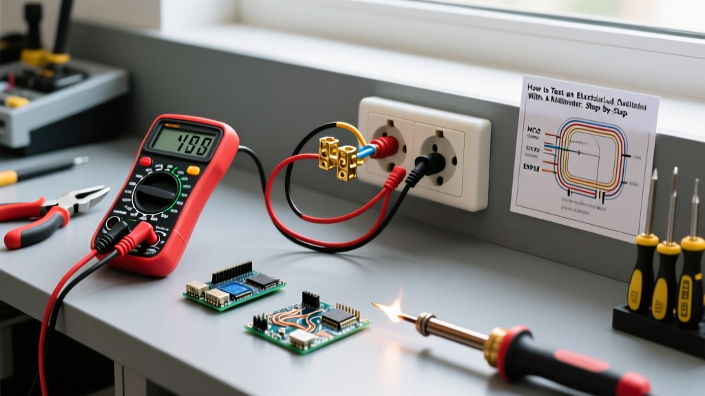
If you are troubleshooting a dead receptacle, verifying a new installation, or hunting down a nuisance tripping GFCI, relying on a basic three-light receptacle tester is a beginner mistake. While those $10 plug-in testers are fine for a quick polarity check, they cannot measure exact voltage drop, identify high-resistance connections, or detect phantom voltages. Learning how to test an electrical outlet with a multimeter provides granular data that separates a guess from a definitive diagnosis.
Standard neon or LED testers draw minimal current and can easily be fooled by 'bootleg' grounds (where the ground terminal is illegally jumpered to the neutral). A digital multimeter (DMM), however, measures the actual electrical potential difference across the circuit's conductors, revealing the true health of the wiring topology. In this comprehensive 2026 guide, we will cover the exact tool specifications required, the OSHA-mandated safety protocols, and the professional 3-point testing sequence used by master electricians.
2026 Multimeter Selection Matrix: Choosing the Right Tool
Before testing live 120V/240V branch circuits, your multimeter must possess the correct safety category rating. According to Fluke's multimeter safety guidelines, you must use a meter rated for at least CAT III 600V for testing standard residential and commercial receptacles. CAT III protects against transient voltage spikes (up to 4,000V) originating from the building's fixed wiring.
| Multimeter Model | Category Rating | Key Features for Outlet Testing | 2026 Est. Price |
|---|---|---|---|
| Fluke 117 True-RMS | CAT III 600V | VoltAlert NCV, AutoV/LoZ (eliminates ghost voltage), True-RMS | $199 - $219 |
| Klein Tools MM400 | CAT III 600V | Auto-ranging, rugged drop-protection, NCV, battery test | $45 - $55 |
| Southwire 100788T | CAT III 600V | Manual ranging, basic AC/DC voltage, continuity, budget-friendly | $28 - $35 |
Expert Recommendation: For professional daily use, the Fluke 117 is the undisputed king due to its LoZ (Low Impedance) mode, which we will discuss in the advanced diagnostics section. For DIYers and weekend warriors, the Klein Tools MM400 offers the best balance of safety, auto-ranging convenience, and affordability.
Pre-Test Safety Protocols & Meter Setup
Testing live circuits carries inherent risks. The OSHA electrical safety guidelines dictate strict protocols for working near exposed energized parts. Even when testing a standard 15A or 20A duplex receptacle, a slip of the probe can cause a phase-to-ground fault, resulting in an arc flash.
Required PPE and Preparation
- Visual Inspection: Inspect your test leads for cracked insulation or exposed copper. Never use damaged leads on live circuits.
- PPE: Wear ANSI Z87.1 safety glasses and voltage-rated gloves if working in damp environments or commercial panels.
- Probe Technique: Hold the probes like pencils. Keep your index finger behind the tactile guard ridge on the probe shaft. Never let your fingers touch the metal tips.
- The One-Hand Rule: When possible, keep one hand in your pocket or behind your back. This prevents a potential shock path from traveling across your chest and through your heart in the event of an accidental contact.
Configuring the Multimeter
- Insert the black probe into the COM (Common) jack.
- Insert the red probe into the V/Ω (Voltage/Ohms) jack. Warning: Never test voltage if the red lead is in the 'A' or 'mA' current jack; this will create a dead short and blow the meter's internal fuse (or worse).
- Turn the rotary dial to V~ or VAC (Alternating Current Voltage).
- If using a manual-ranging meter, set the range to 200V or 600V (the lowest setting that is higher than your expected 120V line voltage).
The 3-Point Receptacle Testing Sequence
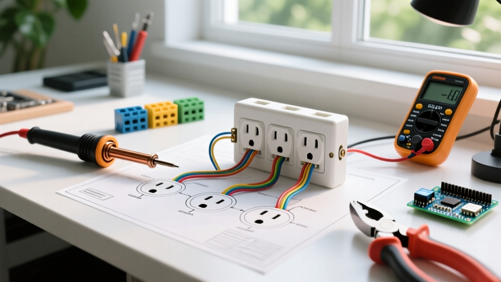
To fully map the health of a standard North American 120V NEMA 5-15R receptacle, you must take three distinct measurements. This method verifies line voltage, ground fault path integrity, and neutral bonding.
Measurement 1: Hot to Neutral (Line Voltage)
Insert the red probe into the shorter, hot slot (the brass-colored terminal side) and the black probe into the longer, neutral slot (the silver-colored terminal side).
- Expected Reading: 118V to 122V.
- Diagnostic Insight: According to the National Electrical Code (NFPA 70), utilities are generally required to maintain voltage within +/- 5% of nominal. A reading below 114V indicates severe voltage drop, an undersized wire run, or an overloaded circuit. A reading above 126V suggests a utility transformer tap issue that can degrade appliance electronics.
Measurement 2: Hot to Ground (Fault Path Verification)
Keep the red probe in the hot slot. Move the black probe to the semi-circular ground hole at the bottom of the receptacle.
- Expected Reading: 118V to 122V (typically identical or within 0.5V of the Hot-Neutral reading).
- Diagnostic Insight: This confirms that the equipment grounding conductor (EGC) is properly bonded back to the main service panel. If this reads 0V while Hot-Neutral reads 120V, you have an Open Ground. The receptacle will power devices, but it will not trip the breaker during a ground fault, presenting a lethal shock hazard.
Measurement 3: Neutral to Ground (Voltage Drop & Bonding Check)
Move the red probe from the hot slot to the longer neutral slot. Keep the black probe in the ground hole.
- Expected Reading: 0.0V to 1.5V.
- Diagnostic Insight: This is the most critical measurement for circuit health. In a properly functioning circuit, neutral and ground are bonded only at the main service disconnect. Under load, the neutral carries current and experiences a slight voltage drop (hence a reading of 0.5V to 1.5V). If you read 0.0V exactly while no load is present, the circuit is healthy. If you read full line voltage (120V), you have a catastrophic wiring fault, such as a bootleg ground or a lost neutral bond at the panel.
Diagnostic Matrix: Decoding Abnormal Readings
Use this troubleshooting matrix to instantly identify the failure mode based on your 3-point test results.
| Hot-Neutral | Hot-Ground | Neutral-Ground | Diagnosis / Failure Mode |
|---|---|---|---|
| ~120V | ~120V | < 2.0V | Normal: Circuit is healthy and correctly wired. |
| ~120V | 0V | 0V | Open Ground: Missing or broken equipment grounding conductor. |
| 0V | ~120V | ~120V | Reverse Polarity: Hot and neutral wires are swapped on the terminals. |
| ~120V | ~120V | ~120V | Bootleg Ground: Ground terminal is illegally jumpered to the Hot wire. |
| 0V | 0V | 0V | Open Hot / Tripped Breaker: No power reaching the receptacle. |
| ~120V | 0V | ~120V | Open Neutral + Bootleg Ground: Dangerous miswiring; immediate shock risk. |
Advanced Edge Cases: Ghost Voltage and LoZ Mode
One of the most confusing scenarios when testing electrical outlets is encountering 'phantom' or 'ghost' voltage. This typically occurs when a hot wire and a disconnected (floating) neutral wire are run parallel inside the same Romex cable for a long distance. The electromagnetic field from the energized hot wire induces a small capacitive voltage onto the floating neutral wire.
A standard high-impedance digital multimeter (which typically has an input impedance of 10 Megohms) will read this induced voltage as real, often displaying anywhere from 40V to 90V on a dead wire. This leads to false diagnostics and unnecessary wall opening.
The Low Impedance (LoZ) Solution
If your multimeter features a LoZ (Low Impedance) setting—such as the Fluke 117—switch to it when testing suspected ghost voltages. LoZ drops the meter's internal impedance to roughly 3 kilo-ohms. This creates a small load on the circuit, instantly draining the capacitively coupled phantom voltage down to 0.0V, while allowing true, hard-wired 120V sources to remain stable.
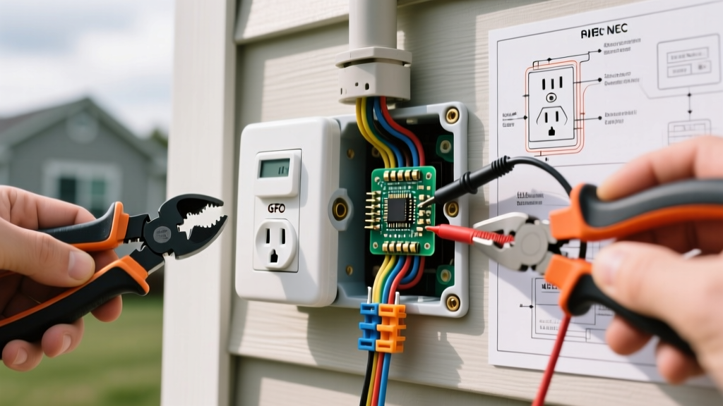
Pro-Tip for 2026 Smart Homes: When testing AFCI/GFCI receptacles, do not rely solely on the built-in 'TEST' button. The internal test button only simulates a ground fault electronically; it does not verify that the physical ground wire is actually connected to the panel. Always perform the Hot-to-Ground multimeter test to ensure physical fault-path integrity.
Frequently Asked Questions
Can I test a 240V dryer or range outlet with the same method?
Yes, but the expected readings change. For a standard NEMA 14-30R (dryer) or 14-50R (range/EV charger), you will test Hot 1 to Hot 2 (expecting ~240V), Hot 1 to Neutral (~120V), Hot 2 to Neutral (~120V), and both Hots to Ground (~120V). Ensure your meter is rated for at least CAT III 600V, as 240V circuits carry significantly higher arc-flash potential.
Why does my Neutral-to-Ground reading fluctuate between 1.5V and 3.0V?
A fluctuating N-G reading usually indicates a shared neutral (multi-wire branch circuit) that is currently under heavy, unbalanced load on the opposing phase, or a loose neutral connection at the panel bus bar. If the voltage consistently exceeds 2.0V under normal household loads, you have excessive resistance in the neutral path that requires immediate tightening or termination repair at the service panel.
Is it safe to test an outlet while appliances are plugged in?
Yes, testing under load is actually preferred for the Neutral-to-Ground measurement, as it reveals voltage drop that isn't visible on an idle circuit. However, ensure you do not bump the appliance's plug or disrupt its connection while inserting your probes into the adjacent duplex receptacle slots.