
The Unique Challenge of Baseboard Receptacles
When you encounter an electrical outlet in baseboard trim or integrated directly into a baseboard heater, you are looking at one of the most abused components in a residential electrical system. Unlike standard wall receptacles positioned at a safe 18 inches above the floor, baseboard outlets endure extreme thermal cycling, heavy dust accumulation, and constant physical strikes from vacuums and furniture. As of 2026, home inspectors and electrical technicians report a disproportionate number of high-resistance faults and thermal degradation failures in these specific locations.
This comprehensive inspection and testing guide will walk you through the exact procedures, National Electrical Code (NEC) requirements, and multimeter diagnostics needed to evaluate the safety and functionality of these specialized receptacles. Whether you are dealing with a factory-integrated heater receptacle like the Cadet R2T2 20-Amp Receptacle Kit or a surface-mounted duplex outlet on wooden trim, the diagnostic principles remain rigorous.
Why Do Baseboard Outlets Exist? Code and Architecture
To properly inspect an electrical outlet in baseboard zones, you must first understand why they are installed. The primary driver is NEC Article 210.52, which mandates that no point along a continuous wall line can be more than 6 feet from a receptacle. In rooms dominated by electric baseboard heaters, placing standard outlets on the wall above the heater poses a severe fire hazard, as lamp cords or appliance cords would drape directly over heating elements that can reach surface temperatures of 160°F to 190°F.
To solve this, the National Fire Protection Association (NFPA) allows for specific exceptions. Under NEC guidelines, receptacles can be integrated directly into the baseboard heater assembly by the manufacturer, or they can be installed in the wooden baseboard trim adjacent to the heater. According to the U.S. Department of Energy, maintaining proper clearance and utilizing integrated receptacles is critical for preventing residential electrical fires caused by cord insulation melting.
The 3 Unique Hazards of Baseboard Receptacles
Before pulling out your multimeter, you must understand the specific failure modes inherent to this location:
- Thermal Loosening (Cold Flow): Baseboard heaters cycle on and off, causing the copper wiring and brass terminal screws to expand and contract. Over 5 to 10 years, this thermal cycling causes terminal screws to lose torque, leading to high-resistance connections and arcing.
- Carbon Tracking from Dust: Floor-level outlets act as magnets for dust, pet dander, and humidity. When dust accumulates across the 120V hot and neutral slots, it can carbonize and create a conductive path, leading to surface arcing and melted faceplates.
- Mechanical Trauma: Vacuum cleaners, mop handles, and shifting furniture routinely crack the polycarbonate or nylon yokes of standard residential-grade receptacles, compromising the internal leaf-spring tension that grips plugs.
Pre-Testing Visual Inspection Checklist
Never skip the visual inspection. According to the U.S. Consumer Product Safety Commission (CPSC), many electrical fires start at the receptacle due to visible, ignored degradation. Turn off the circuit breaker and inspect the following:
- Faceplate Warping: Look for a wavy or melted appearance on the plastic cover plate. This indicates past overheating, likely from a high-draw appliance (like a space heater or vacuum) used while the baseboard heater was simultaneously running.
- Yoke Integrity: Remove the cover plate. Check the metal mounting yoke (strap). If it is bent, or if the plaster ears are broken off, the receptacle will sit unevenly, causing poor plug contact.
- Wire Insulation Condition: Shine a flashlight into the junction box. If the thermoplastic insulation on the 12 AWG or 14 AWG copper wires appears brittle, cracked, or discolored (brown/black), the wire has been subjected to excessive heat and must be stripped back to fresh copper or replaced.
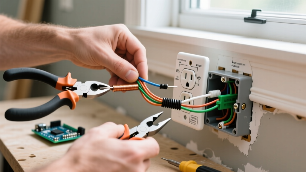
- Backstabbed Connections: If you see wires inserted into the push-in holes on the back of the receptacle rather than wrapped around the side terminal screws, this is an immediate red flag. Backstabbed connections are notorious for failing under thermal cycling.
Step-by-Step Multimeter Testing Guide
Once the visual inspection is complete and the cover plate is removed, restore power to the circuit for live testing. You will need a non-contact voltage tester, a standard 3-prong receptacle tester, and a True-RMS digital multimeter (such as the Fluke 117 or Klein Tools MM400).
Step 1: Verification and Polarity Check
Insert a high-quality receptacle tester (e.g., Gardner Bender GRT-3500) into the outlet. Verify that the lights indicate correct wiring (typically two amber lights). If the tester indicates an open ground or reversed polarity, the circuit must be de-energized and corrected immediately. Note that many older baseboard installations were wired without an equipment grounding conductor; in these cases, the receptacle must be GFCI protected to meet current code.
Step 2: True-RMS Voltage Measurement
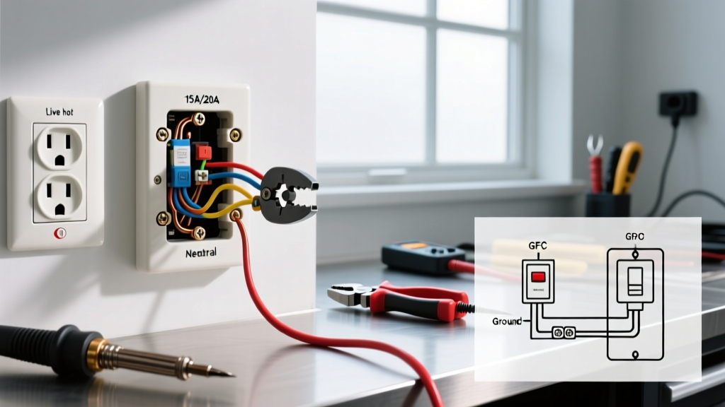
Insert the multimeter probes into the receptacle slots. Hot to Neutral: Should read between 118V and 122V. Hot to Ground: Should read identical to Hot-Neutral. Neutral to Ground: Should read less than 1.5V. A Neutral-Ground reading above 2V indicates a shared neutral, a loose neutral connection upstream, or an overloaded circuit causing voltage drop on the return path.
Step 3: The Load-Based Voltage Drop Test (Critical)
A receptacle might show 120V with no load, but fail catastrophically under load due to loose terminal screws. Plug a known high-draw resistive load into the outlet (such as a 1500W hair dryer or a 12.5A portable heater). While the appliance is running, measure the voltage at the receptacle using your multimeter.
Expert Insight: If the voltage drops by more than 5% (e.g., falls below 114V on a 120V circuit) under a 12A to 15A load, you have a high-resistance fault. This is almost always caused by loose side-terminal screws or degraded backstabbed connections inside the yoke. The receptacle must be replaced and the wires re-terminated.
Failure Modes and Diagnostics Matrix
Use this troubleshooting table to quickly diagnose specific symptoms found during your baseboard outlet inspection.
| Symptom Observed | Probable Root Cause | Actionable Remediation |
|---|---|---|
| Plug falls out easily; loose fit | Worn internal brass leaf-springs due to mechanical abuse from vacuums. | Replace with a Commercial/Spec Grade receptacle (e.g., Leviton 5362) with higher grip tension. |
| Receptacle face feels hot to touch | High resistance at terminal screws; thermal loosening from heater cycling. | De-energize, remove backstabs, strip wire to clean copper, and torque side screws to 14 in-lbs. |
| Brown discoloration on plastic yoke | Arcing or proximity to baseboard heater elements exceeding 90°C rating. | Verify heater clearance. Upgrade to a high-temperature rated nylon receptacle if integrated. |
| GFCI trips randomly when heater turns on | Inductive kickback from heater contactor or shared neutral wiring fault. | Ensure GFCI is on a dedicated circuit or move heater to a separate non-GFCI breaker. |
Remediation and Upgrade Path
If your testing reveals that the electrical outlet in baseboard trim has failed the load test or shows thermal damage, replacement is mandatory. Do not simply swap it for another cheap 50-cent residential receptacle. Baseboard locations demand heavy-duty hardware.
Upgrade to a Commercial Grade (Spec Grade) receptacle, such as the Hubbell 5362 or Leviton 5362-W00. These models feature thicker brass contacts, high-impact nylon faces, and robust steel yokes that resist bending. Furthermore, always use a torque screwdriver set to the manufacturer's specification (typically 14 in-lbs for 12 AWG wire) to ensure the terminal screws will not loosen during the next winter heating season. If the outlet is integrated into a baseboard heater (like a Marley QMark or Cadet unit), ensure you are using the exact OEM replacement receptacle kit designed to handle the specific thermal envelope of that heater chassis.
Frequently Asked Questions
Can I install a standard wall outlet directly above my baseboard heater?
No. NEC guidelines and general fire safety practices strongly prohibit installing standard receptacles directly above baseboard heaters. The rising heat can degrade the receptacle, and cords plugged into it will drape over the hot heating elements, creating a severe fire and shock hazard. Always use integrated heater receptacles or place outlets in the adjacent wood trim at least 6 inches away from the heater ends.
Why does my baseboard outlet have 3 wires connected to one screw?
This is a code violation. Baseboard circuits are often daisy-chained to feed multiple heaters and outlets. If you see two wires under one terminal screw (a 'double tap'), it is only permitted if the screw is specifically listed for it, which standard receptacles are not. You must use a wire nut to pigtail the wires together with a single jumper wire to the receptacle screw.
Do baseboard outlets need to be AFCI or GFCI protected?
It depends on the room and the circuit age. Under modern NEC rules, 120V, 15A and 20A receptacles in living rooms, bedrooms, and hallways require AFCI (Arc Fault) protection. If the baseboard outlet is located within 6 feet of a wet bar, bathroom, or exterior door, GFCI protection may also be required. However, the baseboard heater itself (if hardwired or on a dedicated 240V circuit) does not require GFCI/AFCI protection unless specified by the manufacturer.