
The Critical Importance of Proper Outlet Installation
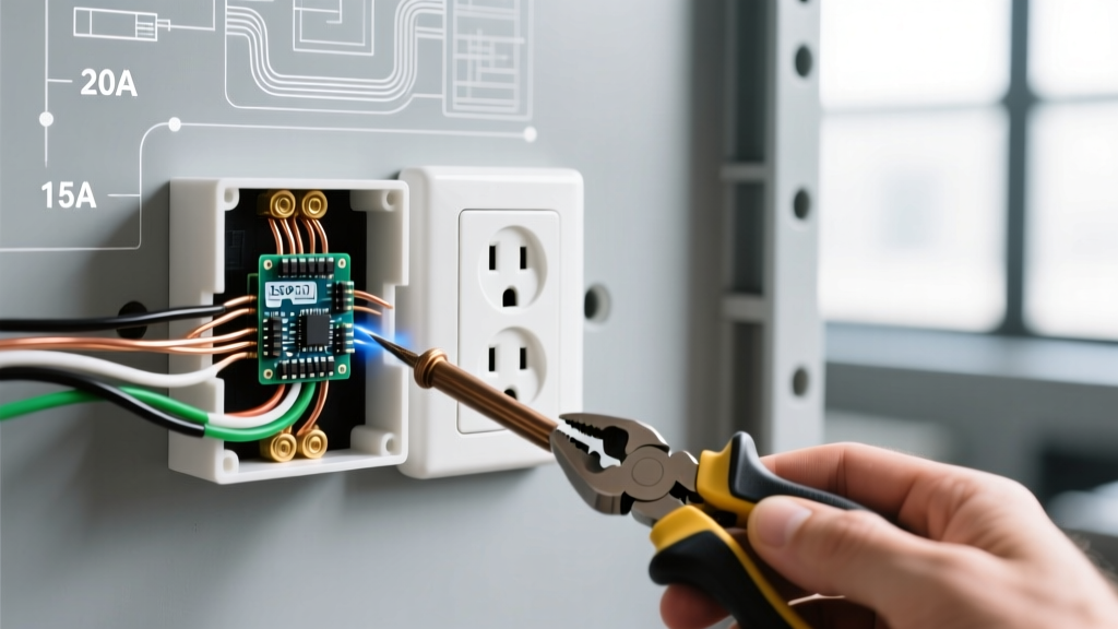
Replacing or installing a new electrical power outlet is a foundational DIY electrical task, yet it remains a leading source of residential arc faults and thermal events when executed poorly. According to the National Fire Protection Association (NFPA), electrical distribution and lighting equipment accounts for roughly 9% of home structure fires, with loose or improper terminations being a primary culprit. In 2026, adherence to the latest National Electrical Code (NEC) is non-negotiable for both safety and insurance compliance.
This comprehensive, step-by-step guide moves beyond basic YouTube tutorials. We will cover the physics of termination, exact torque specifications, NEC box-fill calculations, and the precise methodology required to install a standard 15-amp electrical power outlet that will last for decades without thermal degradation.
Pre-Installation: Code Requirements and Material Selection
Before touching a single wire, you must understand the current code landscape. The NEC mandates that all 15-amp and 20-amp, 125-volt receptacles installed in dwelling units must be Tamper-Resistant (TR). This requirement, detailed in NEC Article 406.12, ensures that internal shutters prevent children from inserting foreign objects into the slots. The Consumer Product Safety Commission (CPSC) strongly advocates for TR receptacles as a baseline safety standard in all modern renovations.
Material and Tool Specifications
Using commercial-grade components rather than builder-grade residential parts drastically increases the lifespan of your electrical power outlet. Commercial spec-grade receptacles feature thicker brass contacts and more robust thermoplastic housings.
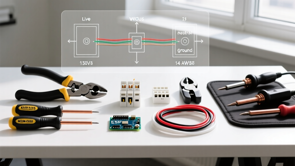
| Item Category | Recommended Specification | Estimated Cost (2026) |
|---|---|---|
| Receptacle | Leviton T52-TR (15-Amp, 125V, TR, Spec-Grade) | $3.50 - $5.00 |
| Wire Stripper | Klein Tools 11063W (Katapult for 14-12 AWG) | $28.00 |
| Torque Screwdriver | Wiha 60601 (10-50 in-lbs, calibrated) | $85.00 |
| Voltage Tester | Fluke 1AC-II or Klein NCVT-3 (Non-Contact) | $25.00 - $35.00 |
| Wire Connectors | Ideal WingNut II (Red, 14-12 AWG) | $0.15 / ea |
Step 1: De-Energize and Verify the Circuit
Safety is the absolute priority. The Occupational Safety and Health Administration (OSHA) emphasizes the "Test Before You Touch" protocol for all electrical work.
- Locate the Breaker: Identify the correct circuit breaker in your main panel. If the panel is unlabeled, use a radio or lamp plugged into the target outlet and turn off breakers until the device powers down.
- Lockout/Tagout (LOTO): Place a piece of electrical tape over the breaker handle to prevent another household member from accidentally turning it back on while you are working.
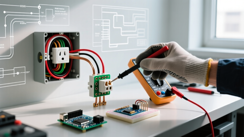
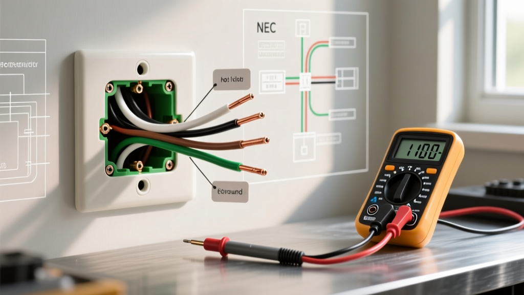
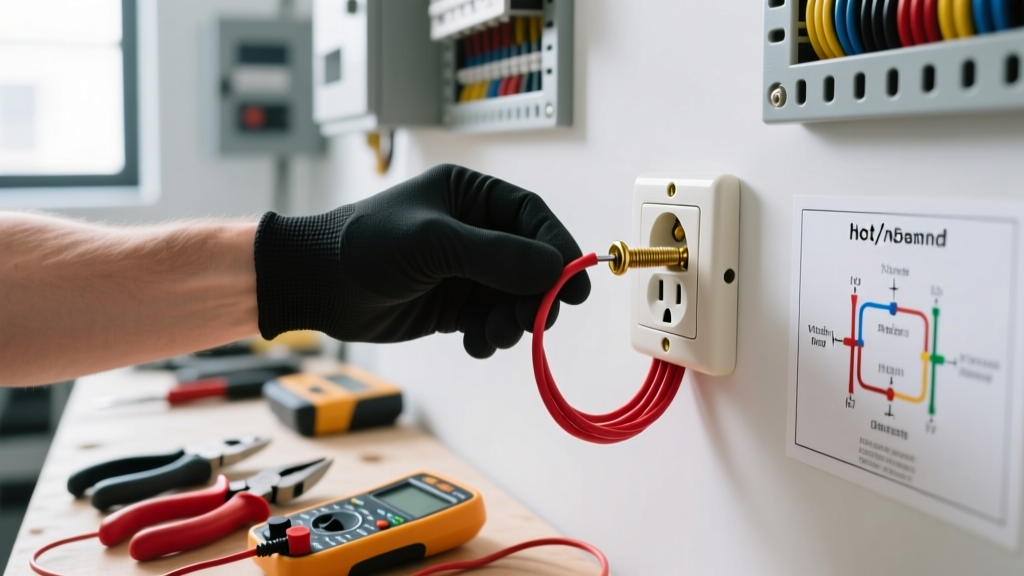
- Verify Zero Voltage: Remove the existing wall plate. Insert your non-contact voltage tester (NCVT) into both the top and bottom slots of the receptacle. Test a known live outlet first to confirm your tester's battery is functional, then test the target outlet. Finally, use a multimeter set to AC Voltage to measure between the hot (brass) and neutral (silver) terminals to confirm a 0.0V reading.
Step 2: Box Fill Calculations and Cable Preparation
Overcrowding an electrical box causes wire insulation damage and traps heat. Under NEC Article 314.16, a standard single-gang plastic nail box (typically 18 to 22 cubic inches) can comfortably hold one 14/2 NM-B cable and one standard 15-amp receptacle. If you are daisy-chaining (feeding through to another outlet), you must account for the internal clamps, the device itself (counts as 2 wire volumes), and the grounding conductors.
Stripping the NM-B Cable
- Strip the outer yellow or white PVC jacket back to exactly 1/4 inch from where it enters the box. Do not leave excessive jacket inside the box, as it consumes valuable cubic inch volume.
- Using your precision wire strippers, remove exactly 3/4 inch of insulation from the black (hot) and white (neutral) conductors. Stripping too little leaves insulation under the terminal screw (a high-resistance fault); stripping too much exposes bare copper outside the receptacle housing (a shock and short-circuit hazard).
Step 3: Forming the Termination Loop
While push-in back-wiring is permitted by code on many modern UL-listed 15-amp devices, professional electricians overwhelmingly prefer side-wiring (screw termination) for its superior mechanical grip and long-term thermal stability.
- Bend the J-Hook: Use the needle-nose pliers built into your wire strippers to bend the exposed copper into a tight, 180-degree J-hook.
- Clockwise Orientation: This is a critical, often-missed detail. The loop must face clockwise. When you tighten the terminal screw (which turns clockwise), the screw head will pull the wire loop tighter around the shaft. If the loop is counter-clockwise, the tightening action will push the wire out from under the screw head, resulting in a loose connection.
- The Pigtail Method: Use a short 6-inch piece of bare 14 AWG copper wire. Connect it to the incoming bare ground wire and the outgoing bare ground wire using a red WingNut connector.
- Device Grounding: Attach the other end of the pigtail to the green grounding screw on the receptacle. This ensures the metal box (if applicable) and the downstream circuit remain grounded regardless of the receptacle's physical presence.
Step 4: Torque Specifications and NEC 110.14(D)
In recent code cycles, the NEC introduced a massive shift in termination requirements to prevent arc faults caused by under-torqued or over-torqued screws.
NEC 110.14(D) states: "Termination torque values shall be applied using a calibrated torque tool... to the values specified by the equipment manufacturer."
For the Leviton T52-TR and most standard commercial-grade 15-amp electrical power outlets, the manufacturer specifies a termination torque of 14 inch-pounds. Over-tightening can strip the brass threads or snap the screw head; under-tightening leads to thermal cycling, oxidation, and eventual arcing. Set your calibrated torque screwdriver to 14 in-lbs and tighten until the tool clicks.
Step 5: Grounding and Pigtailing Best Practices
Never use the receptacle's internal ground strap as the sole path for grounding downstream devices. If the outlet is removed for future maintenance, the downstream ground path is broken, creating a severe shock hazard.
Step 6: Securing the Device and Final Alignment
Fold the wires neatly into the back of the box. Push the hot wires to the back, the neutral wires to the sides, and the ground wires to the bottom. This prevents the ground wire from accidentally shorting against the hot brass terminals when the device is pushed in.
Secure the receptacle to the drywall or plaster ring using the provided 6-32 machine screws. If the outlet sits recessed more than 1/4 inch from the wall surface (common with thick tile or wood paneling), you must use plastic receptacle shims to bridge the gap. A floating outlet will flex when plugs are inserted, eventually loosening the terminal screws over time.
Troubleshooting Common Failure Modes
Even with careful installation, edge cases can arise. Use this matrix to diagnose issues before commissioning the circuit.
| Symptom | Probable Cause | Corrective Action |
|---|---|---|
| Receptacle feels warm to the touch under load | Under-torqued terminal screw causing micro-arcing and increased resistance. | De-energize, inspect for scorch marks. Re-strip wire if damaged, and re-torque to exactly 14 in-lbs. |
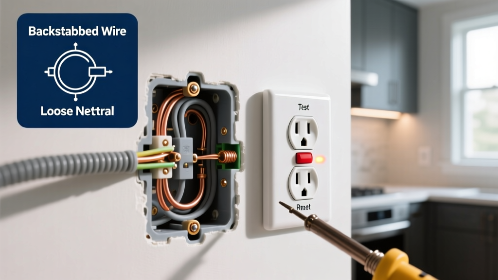
| Tester shows "Open Neutral" | Neutral wire pushed out of backstab hole, or neutral pigtail disconnected in the box. | Remove device, verify the white wire is securely clamped. Switch to side-wiring for a permanent fix. |
| Tester shows "Hot/Neutral Reversed" | Black wire landed on silver screw; white wire landed on brass screw. | Swap the wires. The black (hot) must ALWAYS connect to the shorter slot (brass screw). |
| GFCI trips immediately upon reset | Downstream neutral is shared with another circuit, or neutral is grounded past the GFCI. | Isolate the load-side neutral. Ensure no bare ground wires are touching the neutral pigtails. |
Final Commissioning and Safety Verification
Once the wall plate is installed, restore power at the main breaker panel. Do not immediately plug in high-draw appliances. Instead, use a dedicated receptacle tester like the Klein Tools RT210. This device will verify correct wiring, proper grounding impedance, and the functionality of the TR shutters by requiring simultaneous insertion of the test prongs.
By following this rigorous, code-compliant methodology, your newly installed electrical power outlet will provide safe, reliable service while meeting all 2026 inspection standards. Remember that electrical work carries inherent risks; if your local jurisdiction requires a licensed electrician for permit-pulling or if you encounter aluminum wiring (which requires specialized CO/ALR devices and anti-oxidant paste), consult a professional immediately.