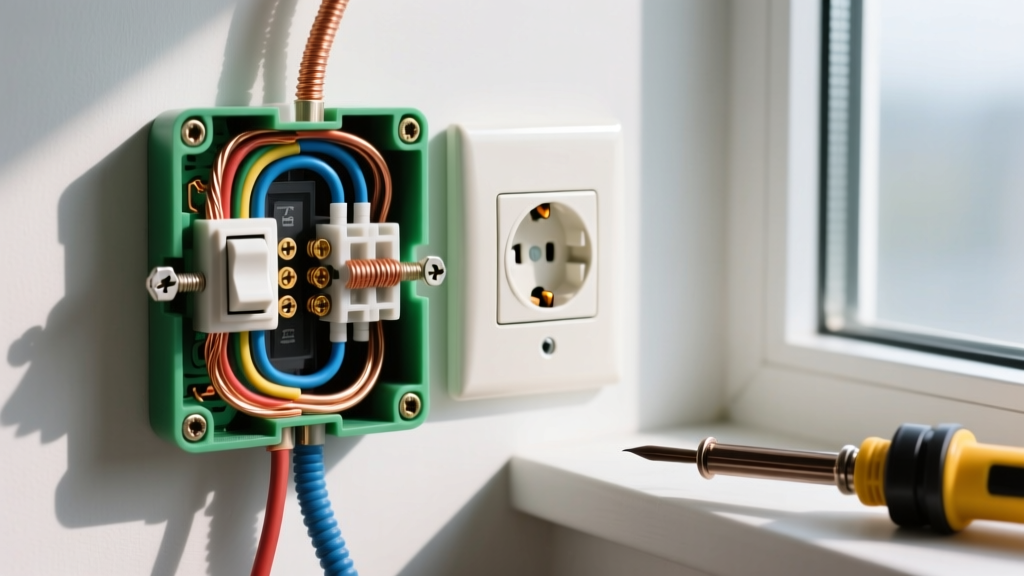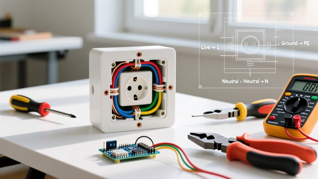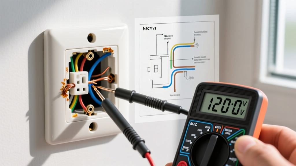

Why Inspect an Electrical Outlet Timer Switch?
While smart home ecosystems dominate modern lighting control, the traditional electrical outlet timer switch remains a critical workhorse for managing heavy-duty inductive loads like pool pumps, patio heaters, and exterior security lighting. However, these devices endure significant thermal and electrical stress. According to the National Fire Protection Association (NFPA), electrical failures or malfunctions are a leading cause of home structure fires. A degrading timer switch can overheat, arc, or fail to disconnect a load, creating a severe fire hazard. This inspection and testing guide provides a rigorous, professional-grade methodology for diagnosing both hardwired in-wall timers and plug-in receptacle timers.
Anatomy of the Switch: Relay vs. Triac Mechanisms
Before connecting a multimeter, you must understand the internal switching architecture of your specific electrical outlet timer switch. The testing methodology changes drastically depending on the component used to interrupt the circuit.
Electromechanical Relays
Heavy-duty timers (like the Intermatic EJ500 or Honeywell RPLS740B) utilize electromechanical relays. These feature physical metal contacts that snap together to pass current. They are ideal for motorized and inductive loads but are susceptible to contact pitting, carbon buildup, and welding if subjected to high inrush currents over time.
Solid-State Triacs
Digital and programmable timers designed strictly for LED or resistive lighting often use Triacs (semiconductor switches). Because they lack moving parts, they are silent and immune to mechanical wear. However, Triacs degrade under high heat and can develop leakage current, allowing a small amount of voltage to pass even when the timer is in the OFF state.
Essential Diagnostic Toolkit for 2026
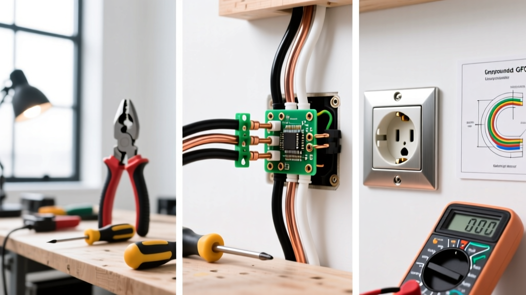
Accurate testing requires precise instrumentation. Do not rely solely on non-contact voltage testers for definitive diagnostics. Assemble the following tools:
- True-RMS Digital Multimeter: A Klein Tools MM400 (approx. $45) or Fluke 117 ($200) is mandatory for accurately measuring AC voltage drops and continuity. True-RMS is critical when testing circuits with non-linear electronic loads.
- Non-Contact Voltage Tester (NCVT): The Klein NCVT-3 ($35) is excellent for initial safety verification to ensure the breaker is fully de-energized.
- Infrared (IR) Thermometer: A basic Seekone IR890D ($25) allows you to scan the faceplate and switch yoke for thermal anomalies without physical contact.
- Plug-In Receptacle Tester: The Sperry Instruments GFI6302 ($15) is necessary for verifying the wiring integrity of the outlet powering a plug-in timer.
Step-by-Step Inspection Protocol: Hardwired In-Wall Timers
Phase 1: Thermal and Visual Inspection (Live Circuit)
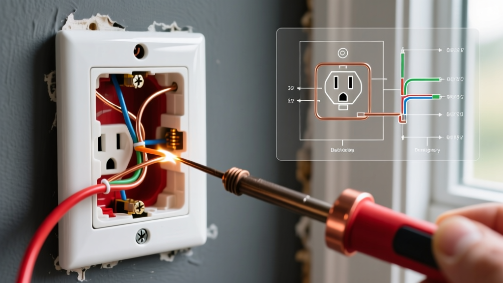
Before cutting power, perform a thermal scan. Point your IR thermometer at the timer faceplate and the surrounding drywall. A healthy switch operating at an 80% rated load (e.g., 12 Amps on a 15-Amp switch) should read within 5 to 10 degrees Fahrenheit of ambient room temperature. If the faceplate registers 115F or higher, the internal contacts are likely pitted and generating excessive resistance heat. Turn off the power immediately.
Phase 2: Voltage Drop Testing (Live Circuit)
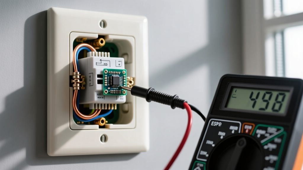
If the timer is currently in the ON position, set your multimeter to AC Voltage. Place one probe on the LINE terminal (incoming hot) and the other on the LOAD terminal (outgoing hot to the fixture). A pristine relay will show a voltage drop of less than 0.5V. If your multimeter reads a drop of 2.0V to 5.0V or higher, the internal contacts are degraded. This voltage drop represents wasted energy converting into heat inside the wall box.
Phase 3: Continuity and Isolation Testing (De-energized)
Shut off the circuit breaker at the main panel. Verify the circuit is dead using your NCVT and multimeter. Remove the timer from the electrical box.
- Test for Welded Contacts: Set the multimeter to Continuity/Ohms. Place probes on LINE and LOAD. Manually force the timer to the OFF state. The meter should read OL (Open Loop) or infinite resistance. If it reads near 0.0 Ohms, the relay contacts have welded together, and the unit is a critical fire hazard.
- Test for Triac Leakage: For solid-state digital timers, standard continuity tests are insufficient. You must test for leakage by wiring the timer in series with a known incandescent test lamp and a temporary power source. If the lamp glows faintly when the timer is OFF, the Triac is failing.
Diagnostic Matrix: Symptoms, Causes, and Solutions
| Observed Symptom | Root Cause Analysis | Required Action |
|---|---|---|
| Load remains ON continuously; manual override fails. | Internal relay contacts have welded shut due to high inrush current arcing. | Replace the electrical outlet timer switch immediately. Upgrade to a higher amperage rating or use a contactor for motor loads. |
| Connected LED lights flicker or emit a faint glow when OFF. | Triac semiconductor degradation causing milliamp leakage current. | Replace the timer with a relay-based model, or install a bleeding resistor (e.g., Lutron LUT-MLC) across the load. |
| Timer loses programmed schedule after brief power outages. | Internal supercapacitor (typically 5.5V 0.47F) or backup battery has degraded past its 5-7 year lifespan. | Replace the battery if user-accessible; otherwise, replace the entire digital timer unit. |
| Audible buzzing or humming from the wall box. | Loose wire termination causing micro-arcing, or a failing electromagnetic coil in the relay. | Tighten terminal screws to 14 in-lbs. If buzzing persists from the switch body, replace the unit. |
Testing Plug-In Electrical Outlet Timer Switches
Plug-in timers (such as the Woods 59720 or BN-LINK digital models) bypass wall wiring but introduce new failure points at the receptacle blades and internal solder joints.
Receptacle and Blade Inspection
Examine the prongs of the timer. Discoloration, pitting, or a melted plastic housing near the blades indicates poor contact tension with the wall receptacle. According to the U.S. Consumer Product Safety Commission (CPSC), loose plug connections are a primary ignition source for residential fires. If the blades show arcing marks, replace both the timer and the wall receptacle.
Load Capacity Verification
Many consumers mistakenly plug space heaters (1500W / 12.5A) into light-duty 15A plug-in timers. The internal trace width on the timer PCB is often only rated for 10A or 1875W. Always verify the manufacturer stamped amperage rating on the back of the unit. Use a Kill A Watt meter to measure the actual draw of the connected appliance; if it exceeds 80% of the timer rated capacity, the internal thermal fuse will eventually blow, or the PCB traces will melt.
NEC Compliance and Box Fill Considerations
When replacing a standard toggle switch with a hardwired electrical outlet timer switch, physical space becomes a major safety factor. Modern digital timers feature deep chassis bodies (often 1.25 to 1.75 inches) to accommodate complex PCBs and heat sinks.
NEC Box Fill Warning: Under NEC Article 314.16, every device and wire clamp counts toward the total box fill volume. A standard 18-cubic-inch single-gang box is frequently too small for a deep-body smart timer, three 12 AWG cables, and wire nuts. Overcrowding crushes wire insulation and traps heat. If your box is tight, upgrade to a 22-cubic-inch deep box or a masonry ring extender before installing the timer.
Furthermore, nearly all modern programmable and smart timers require a neutral wire to power their internal logic boards and Wi-Fi radios. If your older home lacks a neutral wire in the switch box, do not attempt to use the equipment grounding conductor as a neutral. This violates the National Electrical Code and creates a dangerous shock hazard on all grounded metal fixtures in the home. As highlighted by the U.S. Department of Energy guidelines on lighting controls, proper installation of advanced timers not only ensures safety but maximizes the energy-saving potential of automated scheduling.
Final Verification and Commissioning
After installing a new or tested electrical outlet timer switch, perform a full commissioning cycle. Manually cycle the timer ON and OFF five times while monitoring the connected load. Use your IR thermometer to check the switch yoke after 30 minutes of continuous operation under load. Finally, program a test schedule set to trigger 5 minutes in the future, step away, and verify that the internal relay actuates precisely at the designated time. Rigorous testing transforms a simple wall switch into a reliable, fire-safe automation asset.