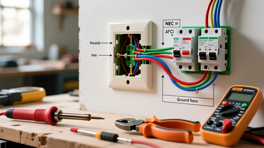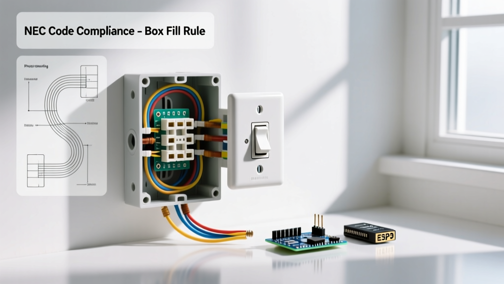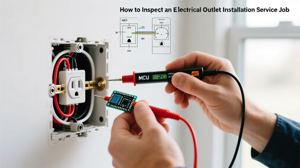

Why Audit Your Electrical Outlet Installation Service?
Hiring a professional electrical outlet installation service is an investment in your home's safety, functionality, and code compliance. However, the assumption that a licensed electrician or contractor will execute flawless work every time is a dangerous fallacy. Rushed jobs, outdated practices, and failure to adhere to the latest National Electrical Code (NEC) updates can leave your home vulnerable to arc faults, ground faults, and electrical fires. In 2026, with the widespread adoption of advanced AFCI/GFCI dual-function receptacles and stricter torque verification mandates, inspecting the completed work is more critical than ever.
This comprehensive inspection and testing guide provides homeowners, property managers, and DIY enthusiasts with a professional-grade protocol to verify the quality of an electrical outlet installation service. By following these steps, you can identify hidden wiring faults, ensure proper torque application, and validate code compliance before signing off on the final invoice.
Phase 1: The Visual and Mechanical Audit
Before touching any testing equipment, conduct a rigorous visual inspection. Many installation errors are immediately visible if you know what to look for.
Faceplate Alignment and Gap Tolerances
According to NFPA 70 (NEC) Article 406.5, receptacle faceplates must effectively cover the outlet box and sit flush against the wall surface. If your installation service left gaps exceeding 1/8-inch, or if the cover plate is cracked from over-tightening, the work fails inspection. Gaps expose the interior of the junction box to dust, moisture, and accidental finger contact.
- Shimming: If the outlet box was set too deep into the drywall, the electrician should have used plastic receptacle shims (like the Ideal Spacers) to bring the yoke flush with the wall. Stacking multiple metal washers is a code violation.
- Plaster Ears: Ensure the plaster ears (the thin metal tabs on the top and bottom of the yoke) were removed if the outlet is being installed in an old-work (remodel) box, as leaving them on can cause the receptacle to sit crooked.
Tamper-Resistant (TR) Shutter Verification
Since the 2008 NEC cycle, all 15A and 20A, 125V and 250V receptacles in dwelling units must be Tamper-Resistant (TR). Look for the 'TR' stamp on the face of the receptacle. To test the mechanical integrity of the internal shutters, attempt to insert a single 3/32-inch wooden dowel or a zip-tie into one of the vertical slots. A properly installed TR receptacle (such as the Leviton R52-05320-W) will physically block the object unless equal, simultaneous pressure is applied to both the hot and neutral slots.
Phase 2: Behind the Yoke - Wiring and Torque Verification
The most critical failures in an electrical outlet installation service occur behind the faceplate, where poor terminations lead to high-resistance connections and thermal runaway.
NEC 110.14(D) Torque Mandates
As of recent NEC cycles, electricians are legally required to use a calibrated torque screwdriver or torque driver to tighten terminal screws to the manufacturer's specified values. For a standard 15-amp duplex receptacle using 14 AWG copper wire, the typical torque specification is 14 inch-pounds (in-lbs). For 12 AWG wire on a 20-amp receptacle, it is usually 16 in-lbs.
Expert Insight: Under-torqued screws cause arcing and heat buildup over time due to micro-vibrations and thermal expansion/contraction cycles. Over-torqued screws strip the brass terminal threads or shear the wire strands, reducing the effective ampacity of the conductor. If your electrician cannot produce a calibrated torque tool or verify the inch-pound settings used, request a re-termination.
Push-In (Backstab) vs. Side-Wiring vs. Back-Wiring
Inspect the side of the receptacle to determine the termination method used by your installation service:
- Push-In (Backstab) Connections: These rely on a small internal spring clip to grip 14 AWG wire. While technically legal for 14 AWG, they are notorious for failing under heavy loads (like space heaters or window AC units) due to minimal surface contact. Recommendation: Reject this method and demand side-wiring or clamp-style back-wiring.
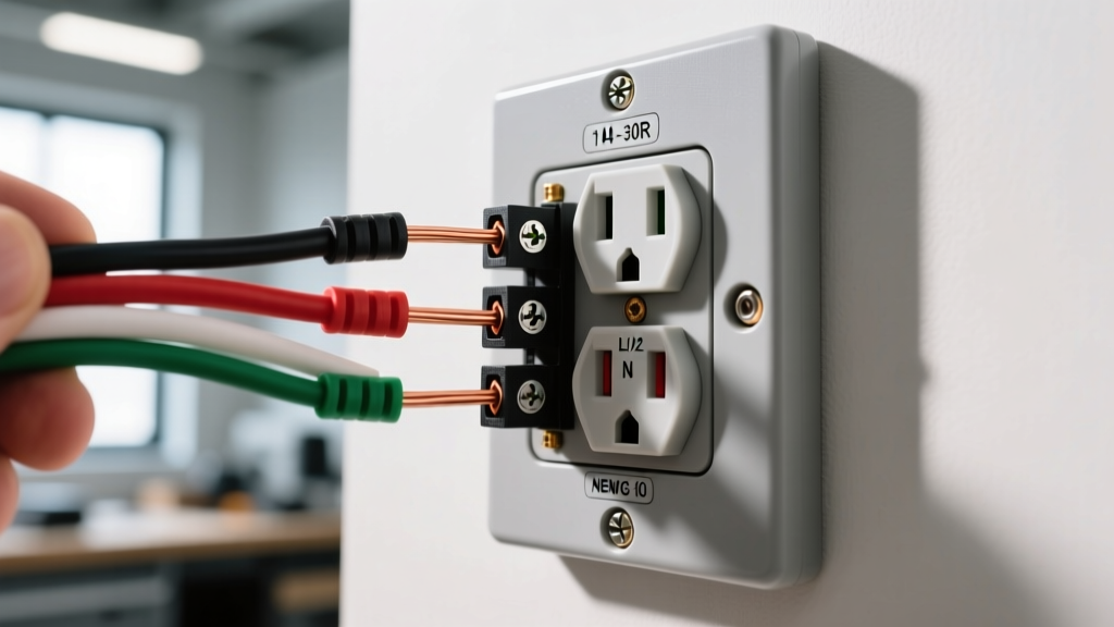
- Side-Wiring (Looping): The wire is stripped, looped clockwise around the terminal screw, and tightened. This is the traditional, reliable method.
- Back-Wiring with Clamps: Found on commercial-grade or high-end residential receptacles (e.g., Hubbell WR5258I), the wire is inserted straight into the back, and a screw tightens a pressure plate against the wire. This is the gold standard for residential installations.
Phase 3: Active Electrical Testing and Measurement
Visual inspections cannot reveal crossed neutrals, bootleg grounds, or voltage drop. You must utilize diagnostic tools to verify the electrical outlet installation service performed the circuit terminations correctly.
Step 1: Receptacle Polarity and Grounding
Use a high-quality solenoid voltage tester or an advanced digital receptacle tester like the Klein Tools RT250. Avoid cheap $10 cube testers with simple neon lights, as they can provide false positives on 'bootleg grounds' (where the installer illegally jumpered the neutral and ground terminals to trick the tester).
Step 2: Digital Multimeter (DMM) Voltage Analysis
Using a True-RMS Digital Multimeter (such as the Fluke 117), perform the following three voltage measurements at the receptacle slots:
- Hot to Neutral (H-N): Should read between 114V and 126V (per ANSI C84.1 standards). If it reads 120V, the circuit is healthy.
- Hot to Ground (H-G): Should read virtually identical to H-N (within 1-2 volts). If H-G is significantly lower than H-N, you have a high-resistance ground path or an undersized ground wire.
- Neutral to Ground (N-G): Should read as close to 0.0V as possible (typically 0.5V to 1.5V under load). If N-G reads 120V, the installer has reversed the hot and neutral wires. If N-G reads 0.0V with no load on the circuit, but jumps to 5V+ when a load is applied, the neutral connection is loose or failing at the panel.
Step 3: GFCI and AFCI Trip Curve Validation
If the electrical outlet installation service installed GFCI (Ground Fault Circuit Interrupter) or AFCI (Arc Fault Circuit Interrupter) receptacles, pressing the 'TEST' button on the device is insufficient. You must verify the trip threshold and timing. According to the U.S. Consumer Product Safety Commission (CPSC) and UL 943 standards, a Class A GFCI must trip within 20 to 30 milliseconds when subjected to a 6mA (+/- 2mA) ground fault. Use a dedicated GFCI tester with a digital readout (like the Amprobe AT-3500) to inject a precise 6mA fault and measure the millisecond trip time.
Diagnostic Matrix: Common Installation Faults
Refer to the table below to diagnose specific failures based on your testing equipment readings. These are the most common errors made by subpar electrical outlet installation services.
| Symptom / Observation | Meter / Tester Reading | Likely Installer Error | Required Remediation |
|---|---|---|---|
| Receptacle trips immediately upon plugging in a lamp. | H-N: 120V H-G: 120V N-G: 0V |
Neutral and Ground bonded at the receptacle (illegal outside the main panel). | Remove the bonding jumper; separate neutral and ground pigtails. |
| Cheap cube tester shows 'Open Ground', but DMM reads 120V H-G. | H-N: 120V H-G: 120V N-G: 0V |
Bootleg ground (Neutral jumpered to Ground terminal to fool testers). | Remove jumper; run a dedicated equipment grounding conductor back to the panel. |
| Voltage drops to 105V when a 1500W space heater is plugged in. | H-N under load: 105V N-G under load: 12V |
Loose neutral termination at the receptacle or upstream junction box; backstab failure. | Re-terminate all neutrals on the circuit using side-wiring or wire nuts with pigtails. |
| Faceplate sits 1/4-inch proud of the drywall. | N/A (Visual) | Outlet box installed too shallow; failure to use box extenders. | Install a plastic box extender ring (NEC 314.20) to bridge the gap safely. |
Phase 4: Code Compliance, Labeling, and Documentation
The final phase of inspecting your electrical outlet installation service involves verifying administrative and labeling compliance.
GFCI/AFCI Labeling Requirements
NEC Article 406.4(D)(4) mandates that all GFCI and AFCI receptacles must be provided with a durable, permanent label indicating 'GFCI Protected' and 'No Equipment Ground' (if installed on an older ungrounded circuit). If your installer replaced old two-prong outlets with GFCIs but failed to apply the UL-listed stickers provided in the receptacle packaging, the installation is technically incomplete and will fail a municipal inspection.
Permit Sign-Off and As-Built Documentation
For any electrical outlet installation service that involves running new circuits, upgrading the panel, or adding outlets in wet locations (kitchens, bathrooms, exteriors), a municipal permit is required. Do not release the final payment until the electrician provides a signed inspection card from the local Authority Having Jurisdiction (AHJ). In 2026, many municipalities utilize digital permitting portals; request the final inspection PDF for your property records.
Conclusion: Protecting Your Investment
An electrical outlet installation service should deliver peace of mind, not hidden hazards. By conducting a thorough visual audit, verifying torque and termination methods, and performing active diagnostic testing with a True-RMS multimeter, you ensure the work meets the highest safety standards. If your testing reveals bootleg grounds, open neutrals, or missing TR shutters, document the faults with photographs and require the contractor to remediate the issues at no additional cost. According to the Fluke Corporation Receptacle Testing Guide, proactive testing is the only definitive way to verify circuit integrity and prevent catastrophic thermal failures down the line.