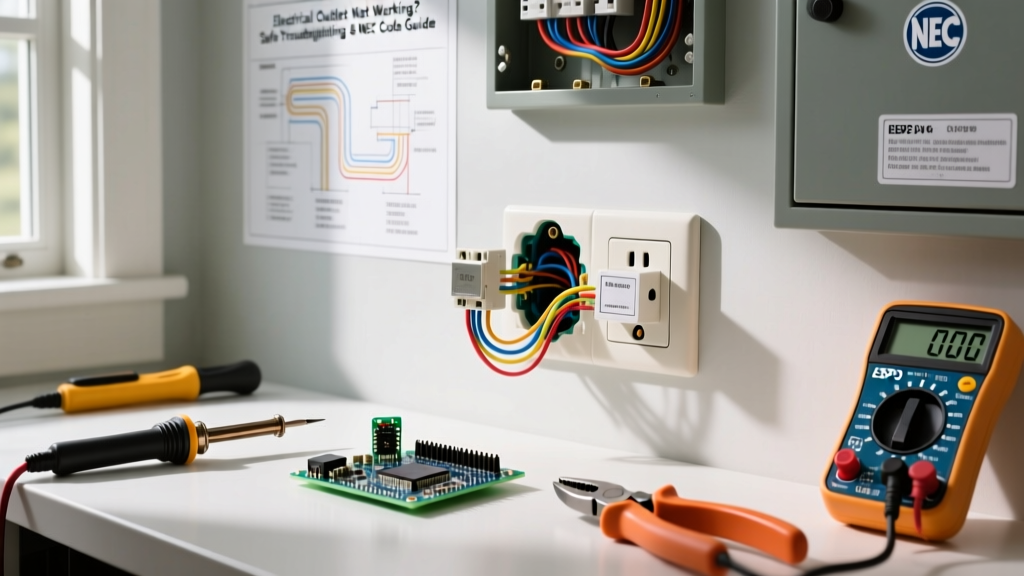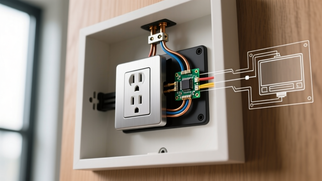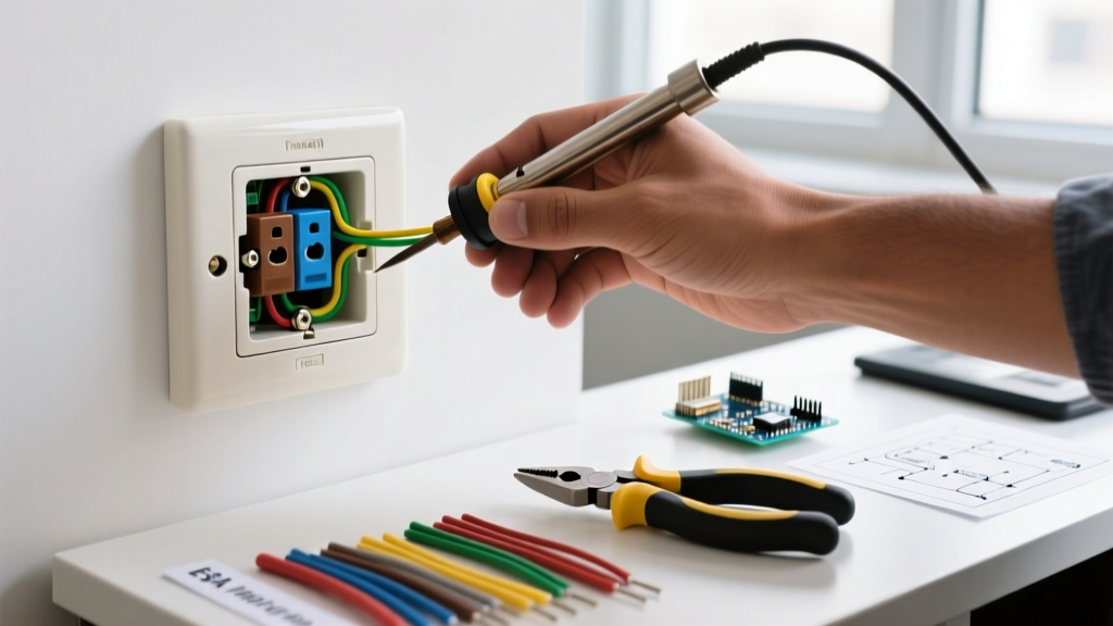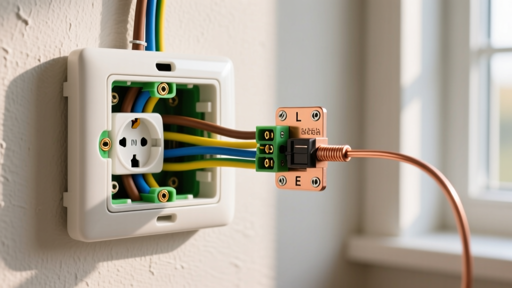

Understanding the Wiring Diagram for a 4 Way Light Switch
Controlling a single lighting fixture from three or more locations requires a specific electrical configuration: two 3-way switches bookending one or more 4-way switches. While a standard single-pole switch simply breaks the hot wire, and a 3-way switch redirects current between two travelers, a 4-way switch acts as an intermediary routing hub. Mastering the wiring diagram for a 4 way light switch is essential for electricians and advanced DIYers tackling large hallways, multi-level staircases, or expansive great rooms.
In this comprehensive 2026 installation guide, we will break down the exact terminal configurations, National Electrical Code (NEC) box-fill requirements, and step-by-step wiring procedures using industry-standard hardware like the Leviton Decora 5604 and Lutron Claro CA-4PS.
Anatomy of a 4-Way Switch: Terminals and Travelers
Before touching a wire stripper, you must understand the physical layout of the switch. Unlike a 3-way switch (which has one common and two traveler screws), a standard 4-way switch features four traveler terminals and one ground terminal. There is no 'common' or 'line/load' terminal on a 4-way switch.
Terminal Color Coding
- Brass Screws (Input Travelers): Typically receive the traveler wires originating from the first 3-way switch.
- Black/Dark Screws (Output Travelers): Typically send the traveler wires onward to the second 3-way switch.
- Green Screw (Ground): Connects to the bare copper or green insulated equipment grounding conductor.
Pro-Tip for Smart Home Upgrades: As of 2026, running 14/3 or 12/3 Romex for physical travelers is becoming less common in new smart-home builds. Systems like the Lutron Caseta bypass the need for a physical 4-way wiring diagram entirely. Instead, you wire a single master smart switch at the line or load location and use wireless Pico remotes at the intermediary locations. If you are retrofitting an older home and lack neutral wires in the switch boxes, traditional mechanical 4-way switches (which do not require a neutral) remain the most reliable and cost-effective solution.
Tools, Materials, and 2026 Pricing
Proper preparation ensures a safe, code-compliant installation. Below is the required bill of materials for a standard 15-amp residential lighting circuit.
| Item | Specification / Model | Estimated Cost (2026) |
|---|---|---|
| 4-Way Switch | Leviton Decora 5604 (15A) or Lutron CA-4PS | $14.50 - $28.00 |
| 3-Way Switches (x2) | Leviton Decora 5603 (15A) | $13.00 each |
| Intermediary Cable | Southwire Romex SIMpull 14/3 (with ground) | $0.85 per foot |
| Line/Load Cable | Southwire Romex SIMpull 14/2 (with ground) | $0.65 per foot |
| Voltage Tester | Klein Tools NCVT-4IR (Non-Contact) | $35.00 |
| Wire Strippers | Klein Tools 11063W (10-22 AWG) | $28.00 |
NEC Box Fill Calculations: Don't Ignore the Math
One of the most common failure points in multi-way switch installations is overcrowding the electrical box. According to the National Fire Protection Association (NFPA) NEC Code 70, specifically Article 314.16, you must calculate the cubic inch capacity required for the box housing the 4-way switch.
Calculating for a 14 AWG 4-Way Box
- The Switch Itself: Counts as 2 wire volumes. (2 x 2.0 cu in = 4.0 cu in)
- Traveler Wires: Four 14 AWG wires terminating in the box. (4 x 2.0 cu in = 8.0 cu in)
- Ground Wires: All equipment grounds combined count as 1 wire volume. (1 x 2.0 cu in = 2.0 cu in)
- Internal Clamps: If present, count as 1 wire volume. (1 x 2.0 cu in = 2.0 cu in)
Total Minimum Box Volume: 16.0 cubic inches. A standard 'deep' single-gang nail-on box (typically 22 cu in) is perfectly adequate, but a shallow 14 cu in remodel box will result in a code violation and a dangerous heat buildup.
Step-by-Step Installation Guide
Follow this sequence to correctly route the line, travelers, and load. For safety, always adhere to OSHA Electrical Safety Standards regarding lockout/tagout procedures before beginning.
Step 1: Power Verification and Prep
Shut off the 15A or 20A breaker at the main panel. Use your Klein Tools NCVT-4IR tester on the existing switches to verify zero voltage. Remove the old switches and pull the wires out of the boxes, straightening them with needle-nose pliers to ensure clean connections.
Step 2: Wiring the First 3-Way Switch (Line Side)
This box receives the main power from the panel via 14/2 Romex.
- Connect the bare copper grounds together with a wire nut and a pigtail to the green ground screw.
- Connect all white neutral wires together with a wire nut. Do not connect the neutral to the switch.
- Connect the black 'hot' wire from the panel to the Common (Black/Dark) screw on the 3-way switch.
- Connect the red and black wires of the outgoing 14/3 Romex to the two Brass (Traveler) screws.
Step 3: Wiring the 4-Way Switch (The Intermediary Hub)
This box will have two 14/3 Romex cables entering it (one from the first 3-way, one heading to the second 3-way).
- Bundle all bare copper grounds and pigtail to the green ground screw.
- Bundle all white neutrals together and push them to the back of the box.
- Take the red and black travelers from the first 14/3 cable and connect them to the Brass (Input) screws on the 4-way switch.
- Take the red and black travelers from the second 14/3 cable and connect them to the Black/Dark (Output) screws on the 4-way switch.
Step 4: Wiring the Second 3-Way Switch (Load Side)
This box connects to the actual light fixture via 14/2 Romex.
- Connect grounds and neutrals as done in previous boxes.
- Connect the red and black travelers from the incoming 14/3 cable to the two Brass (Traveler) screws.
- Connect the black wire heading up to the light fixture (the Load) to the Common (Black/Dark) screw.
Step 5: Final Assembly and Testing
Carefully fold the wires into the boxes using a 'Z-fold' technique to prevent pinching the travelers against the switch terminals. Secure the switches with the provided machine screws, attach the wall plates, and restore power at the breaker. Test the circuit by toggling the light from all three locations in every possible combination.
Troubleshooting Common 4-Way Failure Modes
If the light does not behave correctly after restoring power, consult this diagnostic matrix. Never assume a switch is defective until you have verified the traveler routing.
| Symptom | Probable Cause | Solution |
|---|---|---|
| Light only works from one specific 3-way switch. | A traveler wire was mistakenly connected to the Common screw on a 3-way switch, or travelers are crossed at the 4-way. | Verify that the Line and Load are exclusively on the Common (dark) screws. Ensure travelers are paired correctly. |
| Breaker trips immediately upon flipping a switch. | A hot traveler is shorting against a ground wire, or a neutral was accidentally bonded to a traveler. | Inspect all wire nuts and terminal screws. Ensure no bare copper is exposed outside the terminal clamp. |
| Light works from 3-ways, but the 4-way switch does nothing. | The 4-way switch is wired 'straight through' (input brass to output brass on the same side) rather than crossing the internal circuit. | Swap the two wires on one of the traveler pairs (e.g., swap the red and black on the output side). |
| Flickering or dimming when toggling. | Backstabbing (push-in) connectors were used instead of side-clamp screw terminals. | Remove backstabbed wires and use the screw terminals or shepherd hooks for a high-torque mechanical connection. |
Final Thoughts on Multi-Way Switching
Understanding the wiring diagram for a 4 way light switch bridges the gap between basic DIY and advanced residential electrical work. The key takeaway is that the 4-way switch never interacts with the line voltage or the load directly; it merely swaps the path of the traveler wires. By respecting NEC box-fill calculations, using high-quality 15A rated Decora hardware, and methodically tracking your traveler colors, you will achieve a flawless, code-compliant installation that will last for decades.