
The "Fork" Dilemma: Spade Terminals vs. Traditional J-Hooks
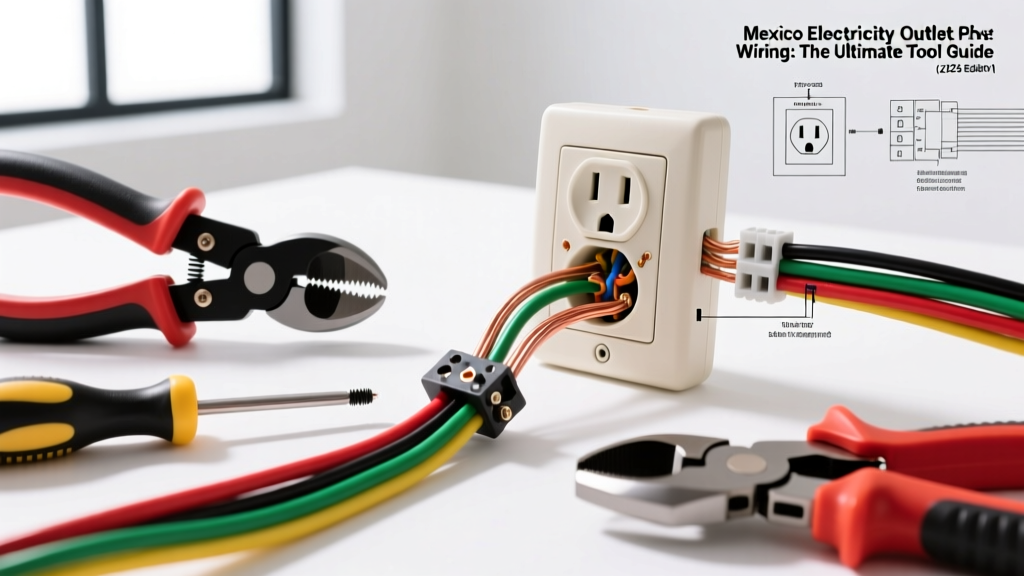
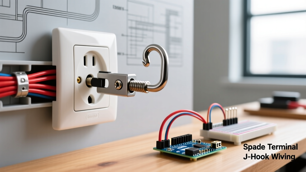
When electrical professionals and advanced DIYers search for a fork in electrical outlet wiring scenarios, they are typically addressing one of two distinct concepts. The first is the physical termination method: using a stamped metal fork terminal (commonly called a spade lug) on the receptacle's binding screws instead of the traditional bare-wire J-hook. The second is the circuit topology: "forking" the circuit conductors via pigtailing to feed both the current receptacle and downstream devices. In 2026, with the National Electrical Code (NEC) placing unprecedented emphasis on torque verification and thermal management, understanding both interpretations is critical for a safe, code-compliant installation.
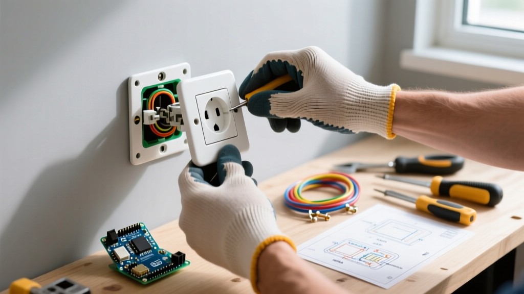
For decades, the standard practice for terminating 14 AWG and 12 AWG solid copper wire on a standard 15A or 20A duplex receptacle (like the ubiquitous Leviton 5362 or Hubbell 5262) was the J-hook method. You strip the wire, bend it into a shepherd's hook, loop it clockwise around the screw, and tighten. However, the fork terminal method—long a staple in industrial control panels—is increasingly being adopted in high-end residential and commercial branch circuits for its superior mechanical stability.
Why Electricians Debate the Fork Connection
The debate centers on shear force and copper creep. A J-hook relies entirely on the friction between the screw head, the bare copper, and the brass terminal plate. If the wire is nicked during stripping, or if the loop is not perfectly centered, the screw head can slice through the copper strands over time, especially under thermal cycling. A properly crimped fork terminal distributes the clamping force evenly across the insulated nylon shoulder and the copper barrel, eliminating the risk of the screw head cutting into the conductor.
NEC Code Reference: According to National Fire Protection Association (NFPA) guidelines in NEC 110.14(A), terminal connections must "ensure a thoroughly good electrical connection without damaging the conductors." Fork terminals inherently protect stranded and solid conductors from screw-head damage during high-torque tightening.
Step-by-Step: Crimping and Securing a Fork Terminal
If you are opting to use fork terminals (such as the Panduit PN14-6F-C or Thomas & Betts RA18-6F for 16-14 AWG wire), precision is non-negotiable. A poorly crimped terminal is a fire hazard. Here is the professional workflow for 2026:
- Select the Right Tooling: Abandon cheap non-ratcheting pliers. Use a ratcheting crimping tool like the Klein Tools 1005 or the IWISS SN-48B. These tools apply a consistent 3,000+ PSI crimp force and will not release until the cycle is complete.
- Strip with Precision: Use a calibrated wire stripper (e.g., Knipex TwinForce) to remove exactly 5/16-inch of insulation. Exposing too much bare wire creates a shock hazard; too little results in insulation being crimped into the copper barrel, causing a high-resistance fault.
- The Crimp and Pull Test: Insert the wire fully into the copper barrel. Crimp the tool. Perform a manual pull test. A proper 14 AWG crimp should withstand over 20 lbs of pull force without the wire slipping.
- Torque to Specification: This is where most DIYers fail. NEC 110.14(D) mandates the use of identified torque tools. Set a calibrated torque screwdriver (like the CDI 401SM) to the manufacturer's specification. For most standard 15A receptacles, this is exactly 14 in-lbs.
Circuit Forking: Pigtailing vs. Daisy-Chaining
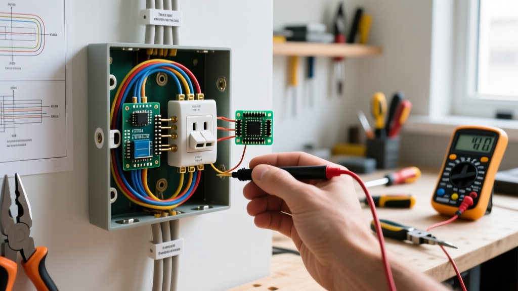
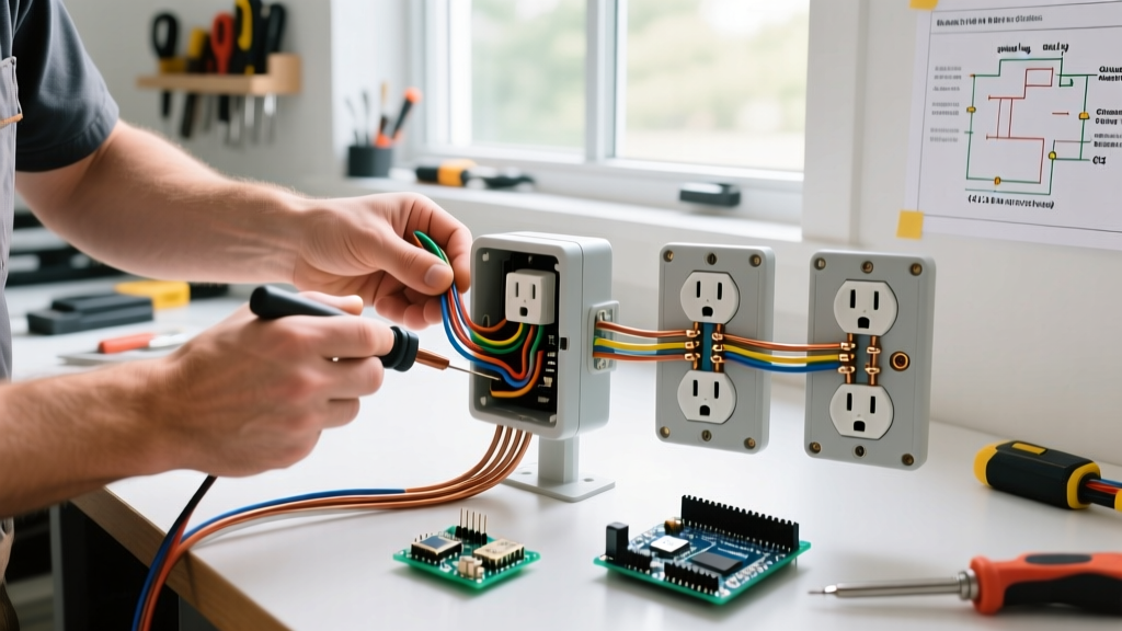
Beyond the physical terminal, "forking" also refers to how the circuit splits at the outlet box. In a traditional daisy-chain, the incoming hot and neutral wires land on one set of outlet screws, and the outgoing wires land on the second set. The outlet itself becomes the bridge for the downstream circuit. In a "forked" or pigtailed scenario, incoming and outgoing wires are spliced together with a short pigtail that feeds the receptacle.
| Feature | Daisy-Chaining (Through-Wiring) | Pigtail Forking (Wire Nut / Push-In) |
|---|---|---|
| Downstream Continuity | Broken if outlet is removed or fails. | Maintained even if outlet is removed. |
| Box Fill Volume | Lower (fewer wire nuts). | Higher (requires pigtails and connectors). |
| Thermal Load on Receptacle | High (carries full downstream load). | Low (only carries local receptacle load). |
| GFCI / AFCI Compatibility | Required for protecting downstream loads. | Used for line-side feed only. |
| 2026 Best Practice | Discouraged for general lighting/outlet circuits. | Strongly recommended by Electrical Contractor Magazine. |
The Modern Push-In Connector Advantage
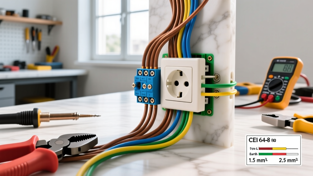
When forking a circuit via pigtailing, the industry has largely moved away from twisted wire nuts in favor of lever-nut connectors like the WAGO 221-3 (3-conductor). These connectors allow you to fork the incoming hot, the outgoing hot, and the receptacle pigtail in a single, transparent, UL-listed housing. They reduce box-fill calculations slightly compared to massive wire nuts and provide a verifiable visual confirmation that all three conductors are fully seated.
Common Failure Modes and Troubleshooting
Whether you are dealing with physical fork terminals or circuit forking, specific failure modes plague amateur installations. Understanding these edge cases separates the professionals from the hobbyists.
- Stranded Wire in a J-Hook: Never wrap bare stranded wire around a receptacle screw. The screw head will splay the strands, reducing the contact area and creating a high-resistance hot spot. If you must use stranded wire (common in solar or RV sub-panels), a fork terminal or pin terminal is mandatory.
- Over-Crimping the Fork Barrel: Using an undersized crimp die on a fork terminal will shear the internal copper strands. This creates a bottleneck that will show up as a 40°C+ delta on a FLIR thermal camera when the circuit is under a 12-amp continuous load.
- The Multi-Wire Branch Circuit (MWBC) Trap: If you are forking a circuit that shares a neutral (MWBC), you must use a handle-tied breaker and must pigtail the neutral in the box. Breaking the neutral path by removing a daisy-chained receptacle on an MWBC will instantly send 240V across your downstream 120V appliances, destroying them.
- Back-Stabbing vs. Fork Terminals: Some DIYers confuse fork terminals with the push-in "back-stab" holes on the rear of cheap receptacles. Back-stabs rely on a weak internal spring clip that is notorious for arcing and failing under heavy loads (like space heaters). Always use the side screw terminals with your fork lugs.
Expert Verdict: When to Use Fork Terminals
For standard residential 12 AWG and 14 AWG solid copper wiring, the traditional J-hook remains perfectly acceptable and code-compliant, provided you are using a calibrated torque screwdriver set to 14 in-lbs. However, the fork in electrical outlet termination method shines in three specific scenarios:
- When terminating stranded copper wire on standard receptacles.
- In high-vibration environments (e.g., outlets mounted on workshop machinery, garage compressors, or RVs).
- When working in deep commercial junction boxes where pre-crimping fork terminals allows for faster, cleaner alignment with recessed receptacle screws.
By combining proper fork terminal crimping techniques with modern WAGO pigtail forking, you ensure that your branch circuits are thermally stable, mechanically robust, and fully aligned with the rigorous safety expectations of the 2026 electrical landscape. For more on grounding and bonding requirements, always consult OSHA Electrical Safety Standards and your local authority having jurisdiction (AHJ).