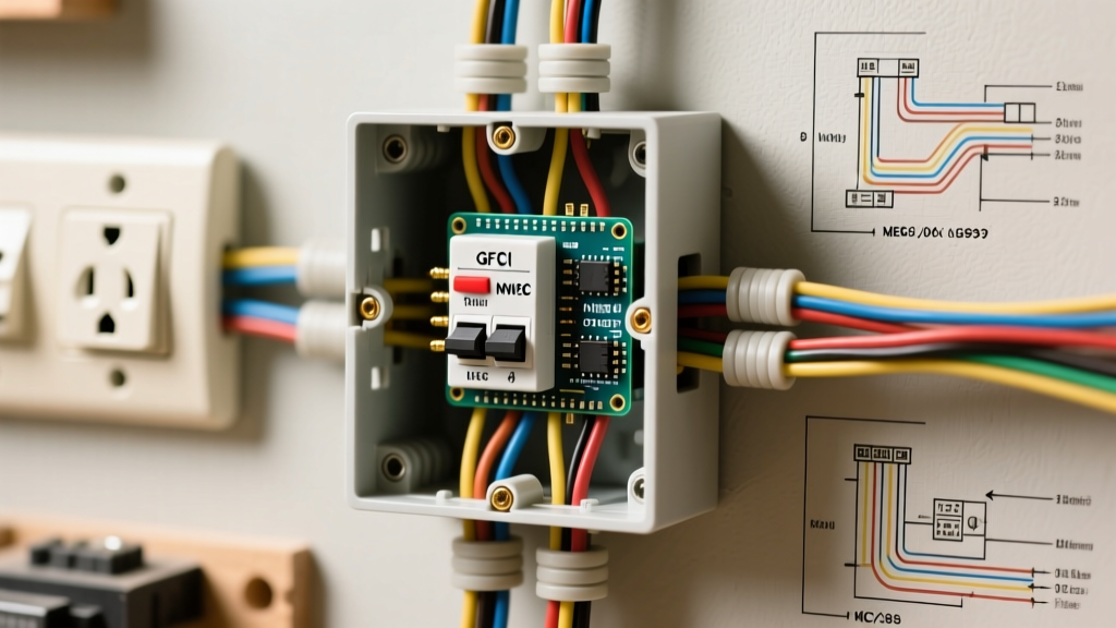

The Critical Role of Outlet Diagrams in Electrical Safety
Misinterpreting a wiring schematic is one of the leading causes of residential electrical fires and failed municipal inspections. When you are planning a new circuit or replacing a faulty receptacle, consulting a precise diagram electrical outlet guide is not just a best practice; it is a fundamental requirement for safety and code compliance. As of the 2026 enforcement cycles, which heavily adopt the latest National Electrical Code (NEC) revisions, inspectors are cracking down on improper terminal connections, inadequate box fill, and missing ground-fault protection. According to the National Fire Protection Association (NFPA), electrical distribution and lighting equipment are consistently responsible for over 30,000 home structure fires annually. Understanding how to translate a 2D diagram into a safe, physical 3D wiring connection is the first line of defense against these hazards.
Decoding the Standard 120V Receptacle Diagram
A standard 15-amp or 20-amp 120V duplex receptacle diagram will always highlight three primary connection points. While it may seem elementary, confusing the line and neutral paths creates a severe shock hazard and can destroy sensitive electronics. Here is how to map the diagram to the physical device:
- Hot (Line) Terminal: The diagram will show the black (or red) insulated wire connecting to the brass-colored screw. This is the ungrounded conductor carrying the 120V potential.
- Neutral Terminal: The white or gray insulated wire maps to the silver-colored screw. This is the grounded conductor, completing the circuit back to the panel.
- Equipment Grounding Conductor (EGC): The bare copper or green insulated wire connects to the green hexagonal screw at the bottom of the yoke.
The 'Backstab' vs. 'Side-Wire' Diagram Discrepancy
Many manufacturer diagrams show quick-wire push-in terminals (backstabs) on the back of the device. Do not use them for code-compliant, permanent installations. While UL-listed, backstabs rely on a spring-metal grip that loosens over time due to thermal expansion and contraction. This creates high-resistance connections, leading to arcing and melted plastic housings. Professional electricians and strict municipal inspectors mandate using the side-wire screw terminals or the rear screw-clamp plates found on commercial-grade receptacles (like the Leviton 5362 or Hubbell 5262 series).
GFCI and AFCI Diagrams: Line vs. Load Mastery
Ground Fault Circuit Interrupter (GFCI) and Arc Fault Circuit Interrupter (AFCI) diagrams introduce a layer of complexity that frequently trips up DIYers: the distinction between LINE and LOAD terminals. The Electrical Safety Foundation International (ESFI) emphasizes that improper GFCI wiring leaves downstream outlets unprotected while giving the false illusion of safety.
Safety Warning: A GFCI receptacle will function and provide power even if the Line and Load wires are reversed. However, the downstream protection will fail, and the device will not pass a standard NEC inspection. Always use the 'LINE' tape provided in the box to cover the load terminals during initial installation to prevent this critical error.
Mapping the GFCI Diagram
- Identify the Source: Use a non-contact voltage tester and a multimeter to confirm which incoming cable is hot. This cable connects exclusively to the brass 'LINE HOT' and silver 'LINE NEUTRAL' terminals.
- Map the Downstream: If your diagram indicates you are protecting additional outlets down the circuit, the outgoing cable connects to the brass 'LOAD HOT' and silver 'LOAD NEUTRAL' terminals.
- Pigtail the Ground: Unlike hot and neutral wires, the bare ground wires from both the line and load cables must be pigtailed together and connected to the single green ground screw on the GFCI.
NEC Compliance Matrix: Outlet Types and Specifications
When reviewing your diagram, you must ensure the physical components match the circuit's amperage and the NEC's protection mandates. The table below outlines the critical specifications for 2026 code compliance.
| Receptacle Type | Wire Gauge Required | Breaker Size | NEC Article Reference | Mandatory Locations (2026 NEC) |
|---|---|---|---|---|
| Standard 15A (TR) | 14 AWG or 12 AWG | 15 Amp | 406.12 (Tamper-Resistant) | All general living areas, hallways, bedrooms |
| Standard 20A (TR) | 12 AWG Only | 20 Amp | 210.21(B)(3) | Kitchen small-appliance circuits, garages, outdoor |
| GFCI 15A/20A | 14 AWG / 12 AWG | 15A / 20A | 210.8(A) | Bathrooms, kitchens, crawlspaces, unfinished basements |
| AFCI / Dual Function | 14 AWG / 12 AWG | 15A / 20A | 210.12 & 406.4(D)(4) | Bedrooms, living rooms (often handled at the breaker panel) |
Multi-Wire Branch Circuits (MWBC): The Shared Neutral Danger
An advanced diagram electrical outlet schematic often features a Multi-Wire Branch Circuit (MWBC). This setup uses two hot wires (typically black and red) sharing a single white neutral wire, fed from a double-pole breaker. This is highly efficient for kitchen islands or workshop benches, but it carries severe risks if wired incorrectly.
If the two hot legs are accidentally placed on the same phase (e.g., both connected to Phase A instead of Phase A and Phase B), the shared neutral will carry the sum of the currents rather than the difference. A 15-amp load on leg A and a 15-amp load on leg B will push 30 amps through a 14 AWG neutral wire, causing it to overheat and melt inside the wall without tripping the breaker.
Code Requirements for MWBC Outlets
According to NEC Article 240.15(B) and 210.4, MWBCs require a simultaneous disconnect. This means the breakers must be tied together with an approved handle tie or be a factory-installed 2-pole breaker. Furthermore, NEC 300.13(B) strictly prohibits using the receptacle's internal metal yoke to daisy-chain the neutral wire. If you remove the outlet to replace it, you cannot break the neutral continuity for the downstream circuit. You must use a wire nut to pigtail the neutral wires together, attaching a single neutral tail to the receptacle's silver screw.
Box Fill Calculations: Sizing the Enclosure
A diagram might show a clean, simple outlet, but the physical reality inside the junction box can be a crowded, dangerous mess. Overcrowded boxes trap heat and make it impossible to safely fold wires without pinching insulation. NEC Article 314.16 dictates strict 'box fill' calculations.
Calculating Cubic Inch Allowances
Before installing the outlet, calculate the volume required by the wires inside the box:
- 14 AWG Conductors: 2.0 cubic inches per wire.
- 12 AWG Conductors: 2.25 cubic inches per wire.
- Equipment Grounds: Count as a single volume allowance based on the largest ground wire in the box (e.g., 2.25 cu in for 12 AWG).
- Clamps: Count as a single volume allowance based on the largest wire.
- The Device (Receptacle): Counts as two volume allowances based on the largest wire connected to it.
Example: If you are wiring a standard 12 AWG outlet with one line and one load cable (4 current-carrying wires, 1 ground, 1 device yoke), the math is: (4 wires x 2.25) + (1 ground x 2.25) + (2 device volumes x 2.25) = 15.75 cubic inches. You must use a deep single-gang box rated for at least 18 cubic inches to remain code-compliant and allow for safe heat dissipation.
Termination Torque: The 2026 Inspection Standard
One of the most heavily enforced updates in recent NEC cycles is Article 110.14(D), which mandates that electrical connections be tightened to the manufacturer's specified torque. Inspectors now frequently require electricians to carry calibrated torque screwdrivers. Relying on 'hand tight' or 'until it stops turning' is no longer acceptable.
For standard 15A and 20A commercial receptacles (such as the Hubbell 5262 or Leviton 5362), the manufacturer specification is typically 14 inch-pounds. Under-torquing leads to loose connections, arcing, and thermal runaway. Over-torquing can strip the brass threads or crush the wire strands, reducing the conductor's cross-sectional area and creating a localized hot spot. Always set your torque screwdriver to the exact value printed on the device's specification sheet before making the final termination.
Final Safety Verification
Once the physical wiring matches your diagram, and all box fill and torque requirements are met, the final step is testing. Never rely solely on a visual inspection. Use a calibrated 3-light receptacle tester with a GFCI trip button to verify correct hot/neutral polarity and proper ground continuity. For GFCI circuits, press the 'TEST' button on the device itself to ensure the internal solenoid physically trips the mechanism. As highlighted by OSHA's electrical safety guidelines, verifying the absence of voltage and the functionality of protective devices is the ultimate safeguard against fatal shock hazards. By strictly adhering to the schematic and the NEC, you ensure a resilient, fire-resistant electrical system that will safely serve the building for decades.