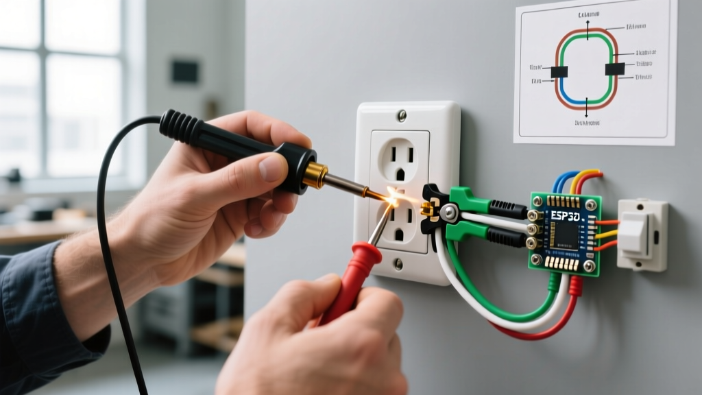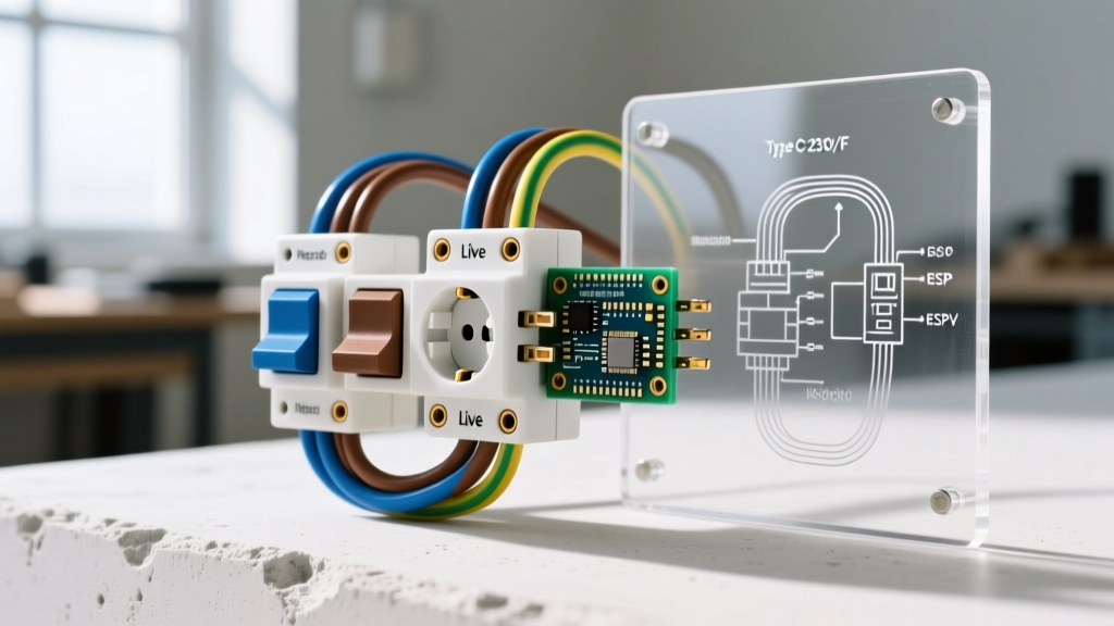

Understanding the 115V Swamp Cooler Circuit Architecture
Wiring an evaporative cooler on your roof or exterior wall requires a precise understanding of motor loads, weatherproofing, and National Electrical Code (NEC) compliance. When technicians and DIYers search for a 115v swamp cooler electrical plug junction box wiring diagram, they are typically trying to bridge the gap between a hardwired branch circuit and the cord-and-plug connection required by the cooler's factory-installed whip. According to the U.S. Department of Energy, evaporative coolers are highly efficient in dry climates, but their induction motors demand rigorous electrical support to prevent thermal overload and voltage drop.
Before pulling any wire, it is critical to clarify a common industry misnomer: while the motor nameplate on your swamp cooler (such as a Hessaire MC18M or Master Cool 7000) will read '115V', the actual branch circuit supply from your panel is nominally 120V. This 5-volt differential is intentional, allowing for a standard voltage drop across long conduit runs without starving the motor. Your junction box setup must be rated for 125V/20A to safely handle the continuous load and the initial locked-rotor inrush current.
Core Components and 2026 Material Pricing
To execute this wiring scenario safely, you cannot use standard indoor residential components. The environment on a roof or sun-baked exterior wall demands NEMA 3R rated enclosures and UV-resistant conduit. Below is the exact bill of materials required for a code-compliant 20-amp junction box setup.
| Component | Recommended Model / Spec | Approx. 2026 Cost | Purpose |
|---|---|---|---|
| Weatherproof Box | TayMac ML500 1-Gang Diecast | $16.50 | NEMA 3R enclosure for wet locations |
| Conductors | 12 AWG THHN Stranded (Black, White, Green) | $0.55 / ft | 20A capacity, stranded for conduit pulls |
| Receptacle | Leviton 5362-W (20A, 125V) | $11.00 | Industrial-grade NEMA 5-20R terminal |
| Conduit & Fittings | 1/2' Liquidtight Flexible Metal (LFMC) | $1.35 / ft | UV/Weather protected physical barrier |
| Cover | TayMac MX1000 Extra-Duty In-Use Cover | $22.00 | Allows plug insertion while sealing out rain |
Visualizing the 115v Swamp Cooler Electrical Plug Junction Box Wiring Diagram
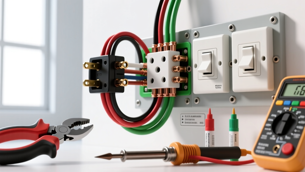
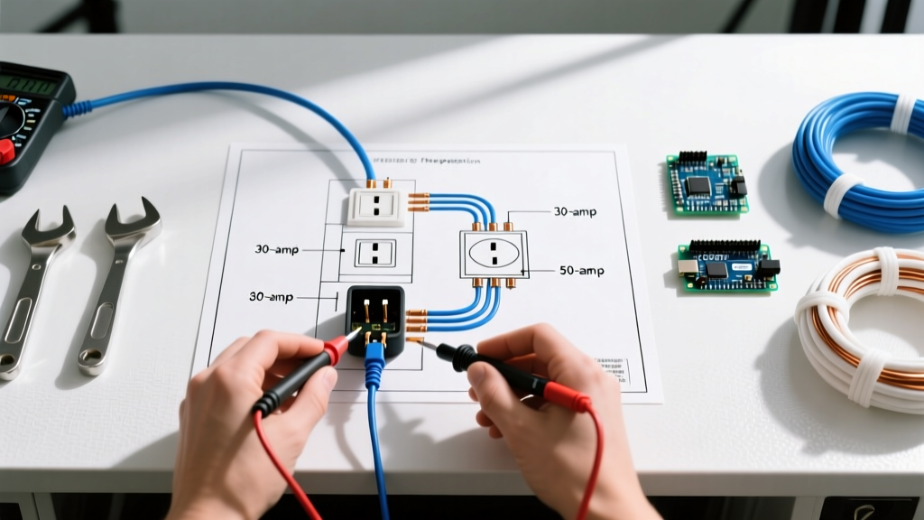
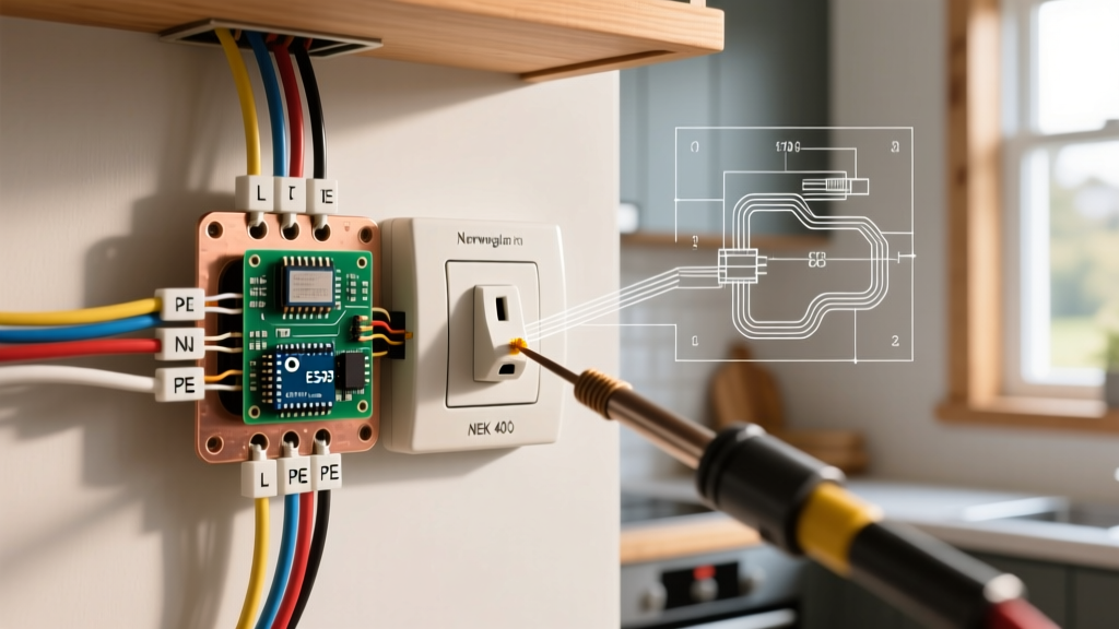
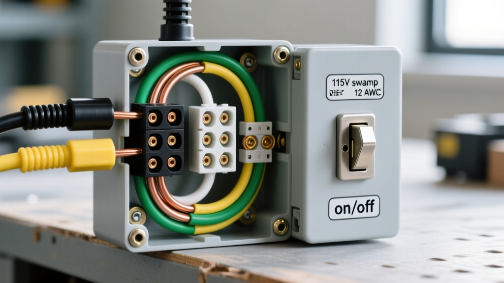
Because physical schematics can vary based on the specific cooler manufacturer, understanding the universal topology of the junction box wiring is essential. The diagram flows from the main service panel, through the conduit, into the junction box, and terminates at the receptacle where the swamp cooler's plug connects.
The Conductor Pathway
- Hot (Line 1): The black 12 AWG THHN wire enters the junction box through the liquidtight conduit fitting. It routes directly to the brass-colored terminal screw on the Leviton 5362-W receptacle. This supplies the 120V nominal phase.
- Neutral (Line 2): The white 12 AWG wire enters the same conduit and terminates on the silver-colored terminal screw. This completes the 115V/120V circuit back to the panel's neutral bar.
- Equipment Grounding Conductor (EGC): The green (or bare copper) wire is the most critical for safety. It must be pigtailed. One end connects to the green grounding screw on the receptacle, while the other end terminates on the internal grounding lug of the diecast TayMac junction box. This ensures the metal box itself remains at zero potential, even if a fault occurs.
Expert Warning: Never use the metal conduit or the metal junction box as the sole grounding path for a swamp cooler. The vibration from the blower motor can loosen conduit fittings over time, breaking the ground continuity. Always pull a dedicated 12 AWG green THHN ground wire. The National Fire Protection Association (NFPA) strictly mandates an equipment grounding conductor within the raceway for this exact reason under NEC Article 250.118.
Step-by-Step Junction Box Termination Procedure
Executing the wiring diagram requires precision. Improper torque or stripped insulation will lead to arcing, which is a primary cause of roof fires in residential evaporative cooling setups.
Phase 1: Prepping the NEMA 3R Enclosure
- Mount the TayMac ML500 junction box to your structural support (e.g., roof joist or exterior stud) using #10 galvanized lag screws.
- Install the 1/2-inch liquidtight conduit fittings into the knockout holes. Ensure you use the provided sealing rings and tighten the locknuts with a conduit wrench until they bite into the metal box, ensuring a watertight seal.
- Feed the three 12 AWG THHN wires (Black, White, Green) through the conduit, leaving exactly 6 inches of slack inside the box, as required by NEC 300.14.
Phase 2: Terminating the Receptacle
- Strip exactly 3/4 inch of insulation from the black and white wires using a precision wire stripper (do not nick the copper strands, which reduces ampacity).
- Form a clockwise J-hook on the exposed copper. This ensures that when you tighten the terminal screw, the hook pulls inward rather than pushing outward.
- Terminate the black wire to the brass screw and the white wire to the silver screw.
- Torque Specification: Use a calibrated torque screwdriver to tighten the terminal screws to 14 inch-pounds. This is the manufacturer specification for 12 AWG wire on Leviton commercial receptacles to prevent thermal loosening.
- Create a 6-inch green pigtail. Connect one end to the receptacle's green ground screw, and splice the other end to the main incoming ground wire and the box's grounding lug using a purple Wirenut (rated for three 12 AWG wires).
Phase 3: Sealing and Testing
Push the wires neatly into the back of the box, folding them in a Z-pattern to avoid pinching the insulation against the sharp edges of the diecast metal. Attach the Leviton receptacle to the box using the provided stainless steel screws. Finally, mount the TayMac MX1000 extra-duty in-use cover. This cover is deep enough to accommodate the swamp cooler's angled plug head while keeping the weather gasket fully compressed.
GFCI Requirements and Motor Inrush Nuances
One of the most heavily debated aspects of the 115v swamp cooler electrical plug junction box wiring diagram is Ground Fault Circuit Interrupter (GFCI) protection. Under recent NEC updates (specifically 210.8(F)), all outdoor receptacles rated 150V to ground or less, 50A or less, require GFCI protection.
However, swamp cooler motors generate significant inrush current (often 3 to 5 times the running amperage) during startup. Standard residential GFCI breakers frequently interpret this inrush as a ground fault, resulting in nuisance tripping every time the cooler's pump or blower kicks on.
The Professional Solution
To maintain code compliance without suffering from nuisance trips, install a GFCI circuit breaker (such as the Square D HOM120GFIC) in the main panel rather than using a GFCI receptacle at the junction box. Panel-mounted GFCI breakers have more robust internal toroids and are slightly less susceptible to the high-frequency transients generated by induction motor startups. Furthermore, keeping the GFCI mechanism out of the extreme heat and UV exposure of the roof significantly extends its operational lifespan.
Common Failure Modes and Troubleshooting
Even with a perfect wiring diagram execution, environmental factors can degrade the system. Use this troubleshooting matrix to diagnose common 115V swamp cooler junction box failures.
| Symptom | Probable Cause | Diagnostic & Fix |
|---|---|---|
| Motor hums but blower won't spin | Severe voltage drop at the junction box | Measure voltage at the receptacle under load. If below 108V, upgrade the branch circuit from 14 AWG to 10 AWG to mitigate long-run voltage drop. |
| GFCI trips immediately on startup | Motor inrush current or moisture in the plug | Verify the cooler plug gasket is seated. If dry, replace the standard GFCI with a time-delay GFCI breaker or ensure the motor start capacitor is not failing. |
| Junction box is hot to the touch | Loose terminal connection (High Resistance) | De-energize circuit. Remove cover and check for melted insulation. Re-terminate wires and torque to 14 in-lbs. |
| Water inside the junction box | Failed conduit seal or missing in-use cover | Replace the conduit sealing rings and apply a bead of exterior silicone around the conduit entry. Ensure the extra-duty cover latch is fully engaged. |
Final Safety Inspections Before Energizing
Before flipping the breaker to the 'ON' position, perform a final visual and mechanical inspection. Verify that no bare copper is exposed outside the terminal screws. Ensure the liquidtight conduit fittings are wrench-tight and that the in-use cover gasket is uniformly compressed against the junction box face. By strictly adhering to this 115v swamp cooler electrical plug junction box wiring diagram and utilizing commercial-grade components, you guarantee a cooling system that operates safely, efficiently, and reliably through the peak heat of the summer season.