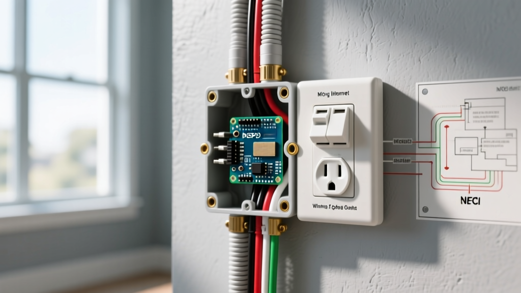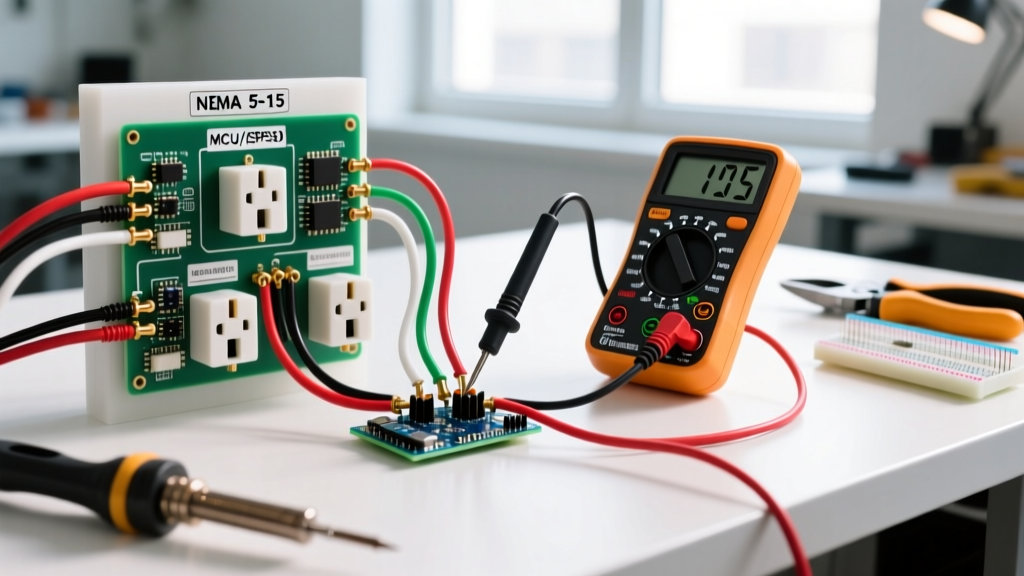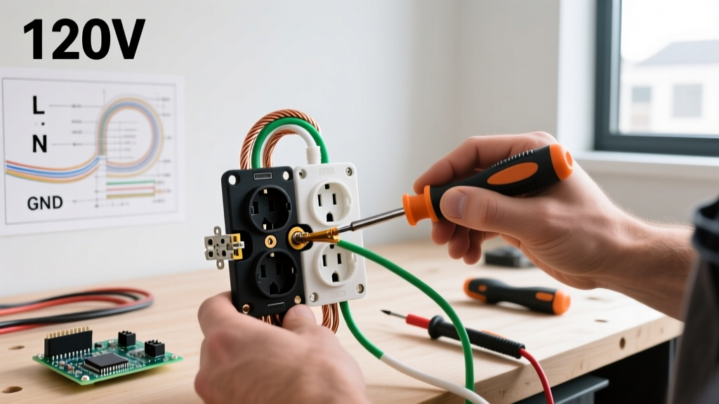

The Evolution of 120V Receptacle Standards
Proper electric socket wiring is the backbone of residential and commercial electrical safety. While the fundamental physics of a 120V duplex receptacle haven't changed, the National Electrical Code (NEC) and manufacturer engineering have evolved significantly. As of the 2023 NEC (and continuing into 2026 enforcement cycles), the focus has shifted heavily toward arc-fault prevention, tamper resistance (TR), and strict torque verification. According to the Consumer Product Safety Commission (CPSC), loose or improperly terminated receptacle connections are a leading cause of residential electrical fires. This guide bypasses generic DIY advice and provides a master-level, step-by-step installation protocol for 15A and 20A 120V receptacles.
Essential Tooling and Material Matrix
Using consumer-grade tools for electric socket wiring often leads to nicked conductors or under-torqued terminals. Professional installations require calibrated, specific tooling.
| Category | Recommended Pro Model | Specification / Purpose | Approx. Cost (2026) |
|---|---|---|---|
| Wire Stripper | Klein Tools 11055 | Precision 12-10 AWG solid wire stripping without scoring copper. | $32.00 |
| Voltage Tester | Fluke T6-1000 | Non-contact and open-jaw voltage/current verification up to 1000V. | $215.00 |
| Torque Screwdriver | Wiha 28502 | Adjustable 10-50 in-lbs; critical for NEC 110.14(D) compliance. | $145.00 |
| 15A Receptacle | Leviton 5362-W | Spec-grade, back-wire clamp, tamper-resistant, 125V. | $6.50 |
| 20A Receptacle | Hubbell HBL5262A | Extra heavy-duty spec grade, brass contacts, auto-ground clip. | $14.00 |
Pre-Installation: Lockout and Box Verification
CRITICAL SAFETY DIRECTIVE: Never rely solely on a non-contact voltage pen. The Occupational Safety and Health Administration (OSHA) mandates the "Test-Before-Touch" protocol. Always use a solenoid tester or a digital multimeter (like the Fluke T6) to verify zero potential between hot-to-ground, hot-to-neutral, and neutral-to-ground before exposing conductors.
Box Fill Calculation (NEC Article 314.16)
Before wiring, verify the electrical box volume. A standard single-gang 18 cubic-inch box can comfortably hold one receptacle, up to four 12 AWG conductors, and one internal cable clamp. If you are pigtailing grounds or neutrals, you must account for the additional wire volume. Overcrowding causes thermal buildup and makes pushing the device into the box dangerously difficult, risking insulation damage.
Step-by-Step Electric Socket Wiring Execution
Step 1: Precision Cable Stripping
Remove the outer NM-B (Romex) jacket exactly 8 inches from the end. When stripping the individual 12 AWG or 14 AWG conductors, use the exact gauge hole on your Klein 11055 strippers. Target strip length: 3/4 inch (19mm). Stripping too short leaves exposed copper outside the terminal; stripping too long creates a shock hazard and increases the risk of a ground fault if the bare copper touches the metal strap.
Step 2: Forming the J-Hook
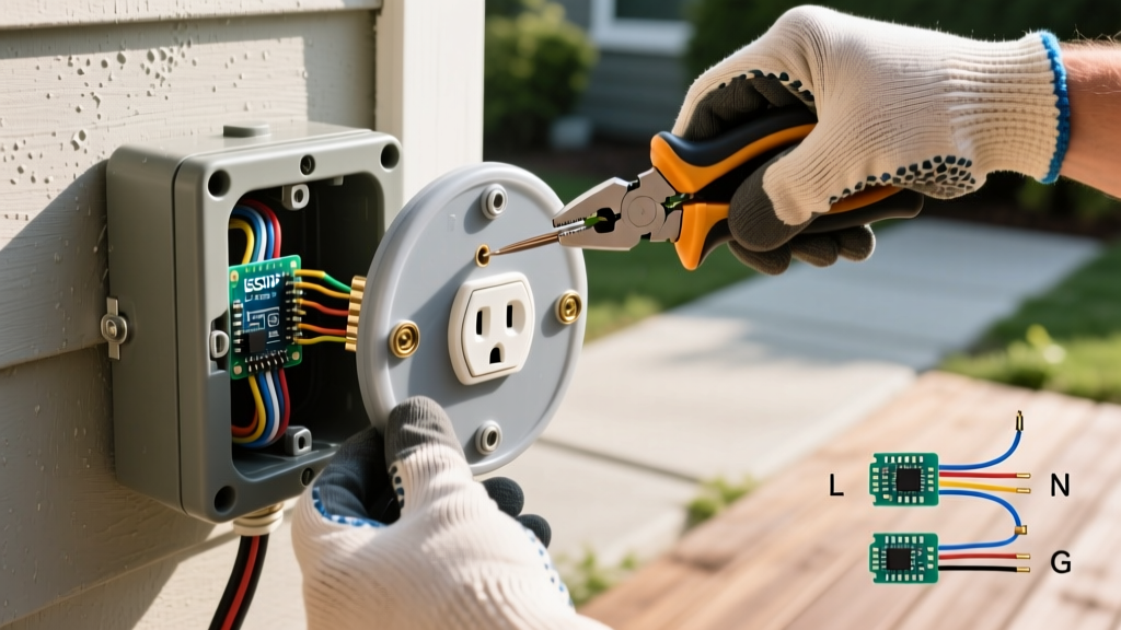
If side-wiring (using the terminal screws rather than the back-wire clamps), bend the stripped copper into a perfect J-hook using the nose of your linesman pliers. The loop must be perfectly round and closed enough to wrap at least 2/3rds of the way around the screw shaft. Crucial detail: Always loop the wire clockwise. When you tighten the screw (which turns clockwise), the loop will naturally close tighter around the shaft. A counter-clockwise loop will be pushed out from under the screw head as it tightens.
Step 3: Termination Method Selection
Modern spec-grade receptacles offer three termination methods. Understanding the difference is vital for long-term reliability:
- Push-In Backstab (Avoid): Found on cheap, builder-grade 15A receptacles. Uses a small spring-metal wedge to grip the wire. These routinely fail under heavy continuous loads (like space heaters) due to thermal cycling, leading to arcing.
- Side-Wire (Acceptable): Wrapping the J-hook around the screw. Reliable if torqued correctly, but prone to human error if the loop is malformed.
- Back-Wire Clamp (Preferred): Found on Leviton 5362 and Hubbell HBL5262 models. You insert the straight stripped wire into the rear hole, and tightening the screw lowers a heavy-duty brass pressure plate onto the wire. This provides maximum surface area contact and is virtually immune to thermal loosening.
Step 4: Torque Application (NEC 110.14(D))
Since the 2017 NEC, and strictly enforced in 2026 inspections, National Fire Protection Association (NFPA) code requires that terminations be tightened to the manufacturer's specified torque using a calibrated tool. "Snugging" it by feel is no longer compliant. Set your Wiha torque screwdriver to the exact specification listed on the back of the receptacle (typically 14 in-lbs for standard 15A/20A devices).
Torque Specifications by Amperage
| Device Type | Wire Gauge | Standard Torque Requirement | Termination Style |
|---|---|---|---|
| 15A Standard Receptacle | 14 AWG Solid | 12 to 14 in-lbs | Side-Wire Screw |
| 15A Spec-Grade Receptacle | 14-12 AWG Solid | 14 in-lbs | Back-Wire Pressure Plate |
| 20A Spec-Grade Receptacle | 12 AWG Solid | 14 to 16 in-lbs | Back-Wire Pressure Plate |
Pigtailing vs. Feed-Through Daisy Chaining
When wiring multiple receptacles on a single circuit, you have two choices: daisy-chaining (feed-through) or pigtailing. While NEC Article 300.13(B) strictly prohibits daisy-chaining the neutral (white) wire through a device in a multiwire branch circuit, best practice for all modern electric socket wiring is to pigtail all conductors.
The Pigtail Method: Use a Wago 221-3 lever nut or an Ideal 33-080 wire nut to connect the incoming line, the outgoing load, and a 6-inch jumper wire (pigtail) of the same gauge. The pigtail then terminates on the receptacle. This ensures that if the receptacle is removed for replacement, the downstream outlets do not lose power, and it drastically reduces box crowding directly behind the device yoke.
Common Failure Modes and Edge Cases
Even experienced DIYers encounter edge cases during socket wiring. Here is how to troubleshoot and prevent the most common failures:
1. Reversed Polarity (Hot/Neutral Swap)
Symptom: A receptacle tester shows "Hot/Neu Reverse".
Cause: The black (hot) wire was terminated on the silver screw, and the white (neutral) on the brass screw.
Fix: The brass screw is always for the hot wire (mnemonic: "Black to Brass"). The silver screw is for the neutral. The green screw is strictly for the bare copper ground. Correct this immediately, as reversed polarity leaves the internal switch of a plugged-in lamp energized even when turned off.
2. The "Bootleg" Ground
Symptom: Tester shows "Correct" wiring, but the ground is fake.
Cause: In older homes, a previous worker may have installed a jumper wire between the neutral silver terminal and the green ground screw to trick a tester.
Fix: Remove the jumper immediately. If no true equipment grounding conductor (EGC) exists in the box, you must either pull new cable with a ground, or install a GFCI receptacle and label it "No Equipment Ground" per NEC 406.4(D)(2).
3. Plaster Ears and Drywall Gaps
Symptom: The receptacle rocks or sinks into the wall when plugging in a tight cord.
Cause: The drywall was cut too large, removing the structural support for the device yoke.
Fix: Do not just overtighten the mounting screws, which will warp the plastic faceplate. Instead, use the "plaster ears" (the removable metal tabs on the top and bottom of the yoke) or install a Caddy TS111 device leveling shim behind the yoke to bridge the gap to the drywall.
Final Inspection and Energization
Once all conductors are torqued, gently fold the wires into the box using an accordion or Z-fold method. Do not jam them in, as this can pinch the ground wire against the hot terminal screw. Secure the device to the box using the provided 6-32 mounting screws. Ensure the yoke is perfectly level before fully tightening. Install a polycarbonate or nylon faceplate (avoid brittle PVC plates that crack when overtightened). Finally, restore power at the breaker and verify operation using a digital multimeter, checking for exactly 120V (+/- 5%) between hot and neutral, and confirming less than 1V between neutral and ground.