
The 2026 Standard for Safe Outlet Removal
Removing an electrical outlet is a common DIY task when renovating a room, relocating furniture, or upgrading to a smart home layout. However, simply ripping a receptacle out of the wall and taping the wires is a severe fire hazard and a direct violation of the National Electrical Code (NEC). Whether you are temporarily removing a duplex receptacle to paint, or permanently decommissioning a circuit branch, you must manage the live wires safely and maintain code compliance.
This beginner tutorial walks you through the exact process of removing electrical outlet hardware, capping the conductors, and securing the junction box. According to the Electrical Safety Foundation International (ESFI), electrical receptacles are involved in thousands of home fires annually, many stemming from improper wire splicing and abandoned junction boxes.
Essential Tools and Materials
Do not attempt this project with improvised tools. Investing in proper electrical testing and termination gear ensures your safety and the longevity of your wiring. Expect to spend around $45 to $60 if you need to purchase the basics.
- Non-Contact Voltage Tester (NCVT): Klein Tools NCVT-3 (approx. $28). Capable of detecting 12V to 1000V AC.
- Wire Strippers: Knipex 1106320 or Milwaukee 48-22-6100 (approx. $25). Must cleanly strip 14 AWG and 12 AWG solid copper.
- Screwdrivers: #2 Phillips and 1/4-inch flathead or 5/16-inch nut driver for yoke screws.
- Wire Connectors: Wago 221 Lever-Nuts (10-pack, approx. $8) or Ideal Wire-Nuts (Tan/Red).
- Blank Cover Plate: Leviton 326-W 1-Gang Blank Nylon Plate (approx. $1.50).
Phase 1: Killing and Verifying the Power
The most critical step in removing electrical outlet components is ensuring the circuit is completely de-energized. Never rely solely on the wall switch or a smart home app to confirm power is off.
- Locate the Breaker: Identify the correct circuit breaker in your main service panel. If your panel is poorly labeled, use a plug-in circuit tracer or a radio turned up loudly to confirm when the power drops.
- Flip and Lock: Switch the breaker to the OFF position. For maximum safety, apply a breaker lockout tag so another household member does not accidentally flip it back on while you are working.
- Test-Before-Touch Protocol: Insert your NCVT into the top and bottom slots of the outlet. The tool should remain silent and unlit. Crucial Step: Immediately test the NCVT on a known live outlet in another room to verify the tester's battery and sensors are functioning correctly.
Phase 2: Extracting the Receptacle
Once power is verified as OFF, you can safely dismantle the hardware.
Step 1: Remove the Faceplate
Use your 1/4-inch flathead screwdriver to remove the center screw holding the faceplate. Gently pry the plate off. If it is painted over, score the perimeter with a utility knife to avoid tearing the drywall paper.
Step 2: Unmount the Duplex Yoke
Remove the top and bottom mounting screws securing the receptacle yoke to the electrical box. These are typically 6-32 machine screws. Pull the receptacle straight out of the box, exposing the wiring.
Step 3: Disconnect the Conductors
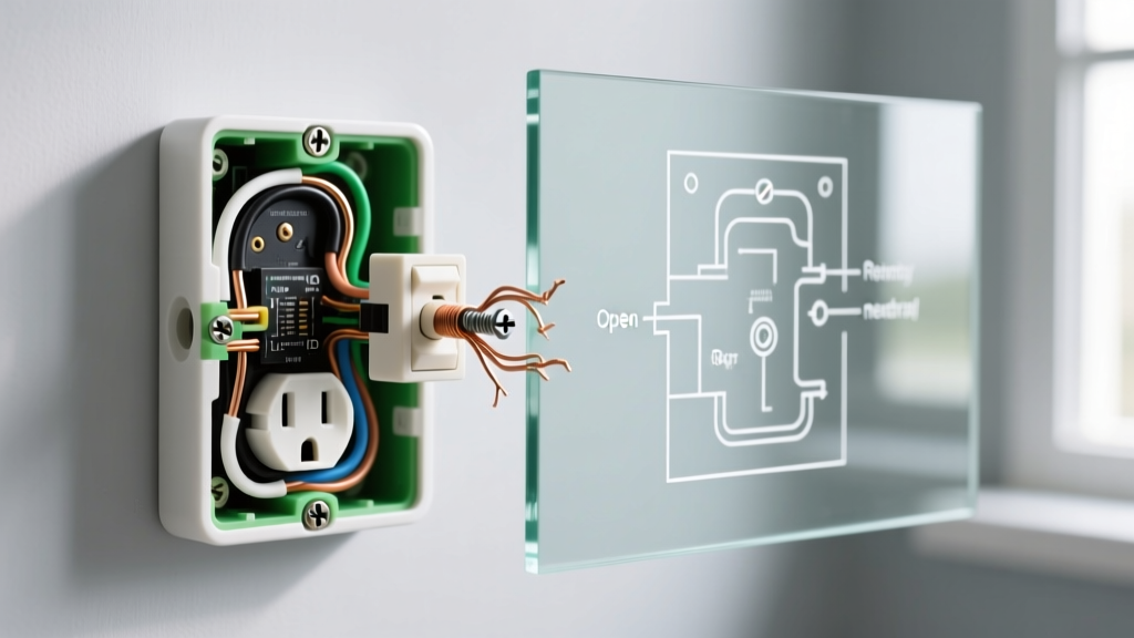
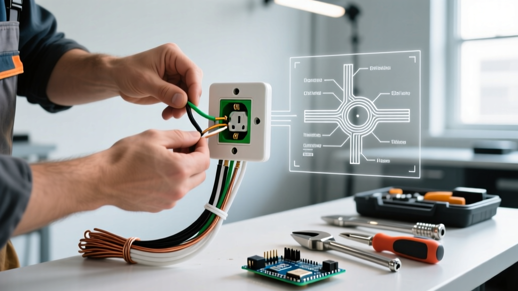
Do not simply yank the wires off the terminal screws, as this can nick the copper or damage the insulation. Loosen the brass (hot), silver (neutral), and green (ground) terminal screws counter-clockwise until the wire loops release. If the wires are back-stabbed (pushed into the rear of the receptacle), insert a small flathead screwdriver into the release slot to free them, or simply snip the wires close to the back of the device if you plan to discard it.
Phase 3: Capping and Securing Wires
If you are permanently removing the outlet but the wires still feed other outlets downstream, you must maintain the circuit's continuity. If the wires are a dead-end branch, you must cap them individually to prevent short circuits.
NEC Code Warning: The National Fire Protection Association (NFPA) mandates that all wire splices must be contained within an approved junction box, and that box must remain permanently accessible. You cannot bury capped wires behind drywall.
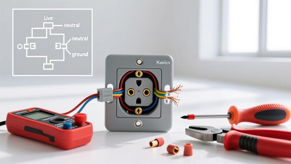
Using Wago 221 Lever-Nuts (Recommended for Beginners)
Traditional twist-on wire nuts require specific torque and twisting technique, which beginners often get wrong, leading to loose connections and arcing. Wago 221 Lever-Nuts eliminate this guesswork.
- Strip exactly 11mm (7/16-inch) of insulation from the end of each wire using your wire strippers.
- Flip the orange lever up on the Wago connector.
- Insert the stripped wire into the transparent housing until it hits the back stop.
- Snap the lever down. The cage clamp secures the wire with exact, repeatable pressure.
Note: Group like colors together. Cap all black (hot) wires together, all white (neutral) wires together, and all bare copper (ground) wires together. If capping a dead-end single wire, use a single Wago 221 or a Tan Ideal Wire-Nut to seal the end.
Wire Connector Sizing Matrix
If you prefer traditional twist-on wire nuts, using the correct size is non-negotiable. An undersized nut will strip the wire; an oversized nut will fall off. Refer to this chart for standard residential Romex (NM-B) cable:
| Wire Gauge | Number of Wires | Ideal Wire-Nut Color | Minimum Strip Length |
|---|---|---|---|
| 14 AWG | 2 to 3 | Yellow | 3/4 inch |
| 12 AWG | 2 | Yellow or Tan | 3/4 inch |
| 12 AWG | 3 to 4 | Red | 3/4 inch |
| 12 AWG / 14 AWG Ground | 2 to 4 | Green (with hole) | 1/2 inch |
Phase 4: Closing the Box
Once the wires are capped, carefully fold them in a 'Z' pattern and push them into the back of the electrical box. Do not crimp or jam them, as this can damage the insulation or push a wire nut off its connection.
Secure a 1-gang blank cover plate over the box using the provided 6-32 screw. This satisfies the NEC requirement for box accessibility while keeping dust, debris, and fingers away from the live terminals.
Troubleshooting Edge Cases and Failure Modes
1. The Multi-Wire Branch Circuit (MWBC) Hazard
When you pull the outlet out, you might see four wires instead of two: Black, Red, White, and Bare Copper. This indicates a Multi-Wire Branch Circuit. The red and black wires are on two separate 120V breakers that share a single neutral (white) wire. Danger: Turning off one breaker will kill the black wire, but the red wire will remain live at 120V. You must locate the handle-tied double-pole breaker in your panel and turn off both halves simultaneously.
2. Aluminum Wiring (1960s-1970s Homes)
If the conductors are dull gray instead of copper color, you have aluminum wiring. Standard copper wire nuts will cause galvanic corrosion over time, leading to high resistance, overheating, and fires. The U.S. Consumer Product Safety Commission (CPSC) strongly advises using only CO/ALR rated devices or AlumiConn lug connectors when terminating aluminum wire. Never use standard Ideal wire nuts on aluminum conductors.
3. Shallow Box Fill Violations
If you are adding multiple Wago connectors to a shallow 1-gang steel box (typically only 1.5 inches deep), you may violate NEC box fill calculations (NEC Article 314.16). Overstuffing the box crushes wire insulation against the metal edges. If the wires and connectors do not fold in easily without extreme force, you must upgrade to a deeper 'old work' box (like the Carlon B618R-UPC, which offers 18 cubic inches of space) before capping and closing.
Final Inspection Checklist
- [ ] Breaker is OFF and verified with a tested NCVT.
- [ ] Receptacle yoke removed without damaging drywall.
- [ ] Wires stripped to exact manufacturer specifications (11mm for Wago).
- [ ] All hot, neutral, and ground wires capped securely with appropriate connectors.
- [ ] Wires folded neatly without pinching or stressing the terminations.
- [ ] Blank cover plate installed securely; box remains accessible.
By following these precise steps, you ensure that removing electrical outlet hardware is done safely, legally, and to the highest standards of modern residential electrical work.