
Decoding the Electrical Wall Outlet Diagram: A 2026 Reference
Whether you are replacing a damaged receptacle in a 1970s home or wiring a new addition, understanding the correct electrical wall outlet diagram is the difference between a safe, code-compliant installation and a severe fire hazard. According to the National Fire Protection Association (NFPA), electrical failures or malfunctions are a leading cause of home fires, often stemming from improper terminal connections or reversed polarity.
This comprehensive wiring diagram reference breaks down the exact terminal mappings, wire gauge requirements, and physical connection methods for standard 15A/20A duplex receptacles, Ground Fault Circuit Interrupters (GFCI), and split-wired (half-hot) configurations. All guidance aligns with the latest National Electrical Code (NEC) standards enforced in 2026.
Anatomy of a Standard 120V Duplex Receptacle
Before tracing any electrical wall outlet diagram, you must understand the physical terminal layout of a standard NEMA 5-15R or 5-20R receptacle (such as the Leviton T5262 or Hubbell 5262 series).
- Brass Screws (Hot): Connects to the black (or red) ungrounded conductor.
- Silver Screws (Neutral): Connects to the white (or gray) grounded conductor.
- Green Screw (Ground): Connects to the bare copper or green insulated grounding conductor.
- Break-Off Fins (Tabs): Located on the sides of the yoke, these metal tabs connect the top and bottom receptacles. Removing them allows for split-wiring or switch-looping.
Standard 15A/20A Electrical Wall Outlet Diagram
The standard receptacle diagram represents a simple series pass-through or an end-of-run termination. Below is the visual mapping for an end-of-run standard outlet.
Wiring Mapping Matrix
| Wire Color | Function | Receptacle Terminal | Connection Method |
|---|---|---|---|
| Black | Hot (Ungrounded) | Brass Screw | Hook clockwise under screw or back-clamp |
| White | Neutral (Grounded) | Silver Screw | Hook clockwise under screw or back-clamp |
| Bare / Green | Equipment Ground | Green Screw | Hook clockwise, ensure no bare wire touches yoke |
Pass-Through (Daisy Chain) Variation: If the outlet is in the middle of a circuit run, you will have two 14/2 or 12/2 NM cables entering the box. Connect both black wires to the two brass screws (or pigtail them together with a wire nut and a single 6-inch black jumper to one brass screw). Do the same for the white wires on the silver screws, and the bare wires on the green screw (or use a green grounding pigtail clip).
GFCI Receptacle Diagram: Line vs. Load Demystified
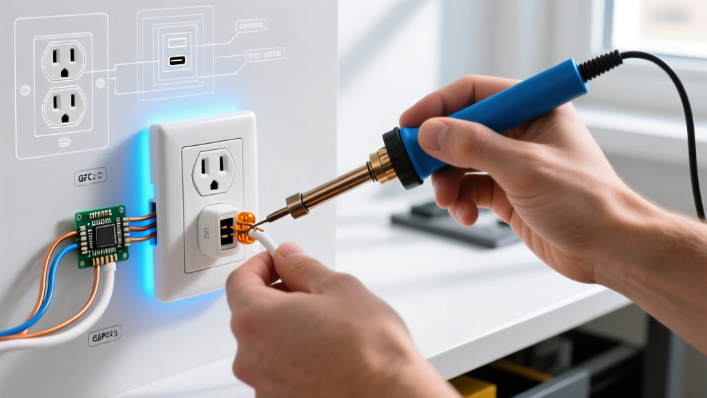
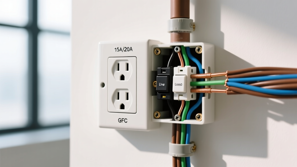
GFCI receptacles (e.g., Leviton GFNT2-W) are mandated by NEC Article 210.8 for wet and damp locations, including kitchens, bathrooms, garages, and outdoors. The most common point of failure in DIY electrical work is misinterpreting the GFCI electrical wall outlet diagram, specifically the LINE and LOAD terminals.
GFCI Terminal Mapping
LINE Terminals (Power IN): These connect to the wires bringing power directly from the breaker panel. The black wire goes to the brass LINE screw; the white wire goes to the silver LINE screw.
LOAD Terminals (Power OUT): These connect to downstream standard outlets that you want to protect with this single GFCI. If you have a second cable leaving the box to feed another outlet, its black wire goes to the brass LOAD screw, and its white wire goes to the silver LOAD screw.
The 'Won't Reset' Failure Mode: If you accidentally connect the main panel feed to the LOAD terminals instead of the LINE terminals, the GFCI will not power up, and the reset button will fail to engage. Furthermore, the Consumer Product Safety Commission (CPSC) notes that improperly wired GFCIs may fail to trip during an actual ground fault, leaving users vulnerable to lethal shock.
Split-Wired (Half-Hot) Outlet Diagram
A split-wired outlet is commonly used in living rooms or bedrooms where one half of the duplex receptacle is controlled by a wall switch (for a lamp), while the other half remains constantly hot for electronics.
Step-by-Step Split Wiring Execution
- Prepare the Yoke: Use needle-nose pliers to snap off the brass break-off tab on the hot side of the receptacle. Do not break the silver tab on the neutral side.
- Run 3-Wire Cable: You must use a 3-conductor cable (e.g., 14/3 or 12/3 NM-B) from the switch to the outlet box. This provides a constant hot (black), a switched hot (red), and a shared neutral (white).
- Connect the Hots: Connect the constant hot (black) wire to the top brass screw. Connect the switched hot (red) wire to the bottom brass screw.
- Connect the Neutral & Ground: Connect the white wire to either silver screw (the intact tab bridges them). Connect the bare ground to the green screw.
Wire Gauge, Breaker, and Receptacle Compatibility
An electrical wall outlet diagram is useless if the physical components are mismatched. NEC 210.21(B)(3) strictly dictates receptacle ratings based on circuit amperage.
| Circuit Breaker | Copper Wire Gauge | Allowed Receptacle Rating | Typical Application |
|---|---|---|---|
| 15 Amp | 14 AWG | 15 Amp ONLY | Bedrooms, Living Rooms, Hallways |
| 20 Amp | 12 AWG | 15 Amp OR 20 Amp | Kitchens, Bathrooms, Garages, Outdoors |
| 30 Amp | 10 AWG | 30 Amp (e.g., NEMA L6-30R) | Dryers, RV Plugs, Heavy Machinery |
Note: You can install a 15A receptacle on a 20A circuit (as the 15A plug blade configuration prevents a 15A device from drawing 20A), but you cannot install a 20A receptacle (which has a T-shaped neutral slot) on a 15A circuit wired with 14 AWG wire.
Multi-Wire Branch Circuits (MWBC) and Split Outlets
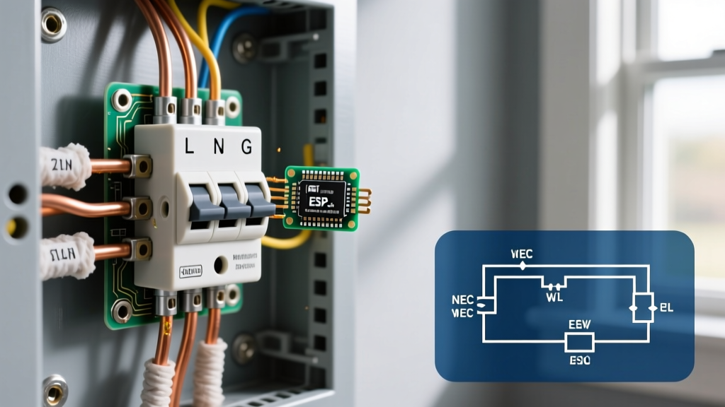
When utilizing a split-wired diagram powered by an MWBC (two hot wires sharing a single neutral wire from a 240V breaker), extreme caution is required. The two hot wires must be on opposite phases (legs) of the electrical panel to prevent overloading the shared neutral. Furthermore, NEC 210.4(B) requires a simultaneous disconnect mechanism—meaning you must use a 2-pole breaker or an approved handle-tie on two single-pole breakers. This ensures that an electrician working on the outlet doesn't turn off one breaker, assume the box is dead, and get shocked by the second live leg.
Troubleshooting Common Diagram Errors
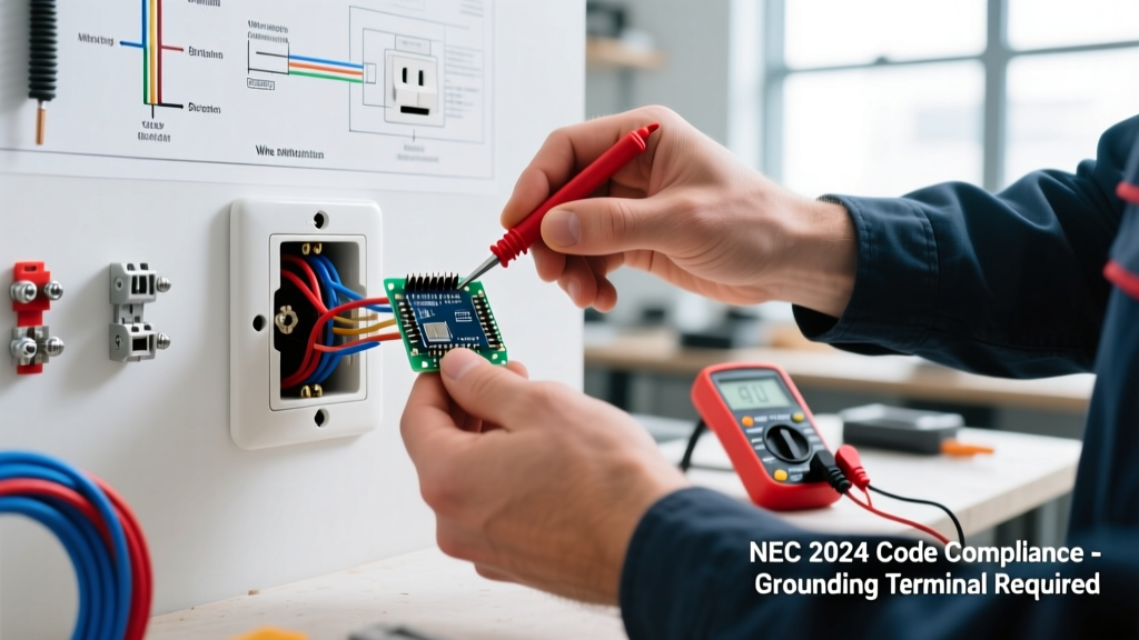
Even with a perfect electrical wall outlet diagram in hand, physical installation errors occur. Use a digital multimeter or a commercial receptacle tester (like the Sperry Instruments GFI-6302) to verify your work.
- Reversed Polarity: Hot and neutral wires are swapped. The white wire is on the brass screw, and the black is on the silver. This leaves the lamp socket threaded sleeve energized, posing a shock hazard when changing bulbs.
- Open Ground: The bare wire is not making solid contact with the green screw, or the grounding path back to the panel is broken. AFCI and GFCI breakers may nuisance trip if the ground reference is unstable.
- Hot-Ground Reverse: A rare but dangerous fault where the hot wire is connected to the ground screw, energizing the entire metal faceplate and any connected appliance chassis.
Frequently Asked Questions (FAQ)
Can I wire multiple outlets to the LOAD side of a GFCI?
Yes. The LOAD terminals on a GFCI receptacle are designed to protect all downstream standard outlets on the same circuit. This is highly cost-effective compared to buying multiple GFCI receptacles. However, if the upstream GFCI trips, all downstream outlets will also lose power, which can cause confusion for homeowners troubleshooting 'dead' outlets in adjacent rooms.
Do I need to use pigtails in an electrical box?
While you can use the two sets of screws on a standard receptacle to pass power to the next outlet, using wire nuts and pigtails is considered best practice by master electricians. Pigtailing ensures that if the receptacle fails or is removed, the downstream outlets do not lose power. It also reduces the physical bulk of wires stuffed behind the yoke, lowering the risk of pinched insulation.
What torque should I use for outlet screws?
Most modern 15A and 20A receptacles from manufacturers like Leviton and Hubbell specify a terminal torque of 12 to 14 inch-pounds. Overtightening can strip the brass screw head or damage the internal yoke, while undertightening leads to thermal expansion loosening the wire over time. As noted by OSHA electrical safety guidelines, loose connections are a primary precursor to electrical arcing and subsequent fires.
Pro Tip for 2026 Installations: When upgrading older homes, always check the depth of the electrical boxes. Modern GFCI and AFCI receptacles are significantly deeper (often exceeding 1.5 inches) than standard 1980s receptacles. If your boxes are only 2 inches deep, you will struggle to fold the wires and may need to install box extenders to meet NEC 314.20 flush-mount requirements.