
Introduction: Decentralized Power and the Modern Solar Receptacle
As photovoltaic component costs continue to drop through 2026, wiring a dedicated solar powered electrical outlet in off-grid sheds, workshops, and ADUs (Accessory Dwelling Units) has transitioned from a niche DIY experiment to a standard residential electrical project. However, a solar-powered receptacle is not a standalone device; it is the termination point of a carefully balanced microgrid. Whether you are routing 120V AC from a pure sine wave inverter or running 12V DC directly from a charge controller's load terminals, the wiring scenarios demand strict adherence to voltage drop calculations, NEC (National Electrical Code) guidelines, and proper grounding topologies.
In this guide, we break down the two most common wiring scenarios for solar-fed outlets: the 120V AC inverter-fed circuit for standard appliances, and the 12V DC direct-wire scenario for specialized off-grid applications. We will cover exact wire gauges, breaker sizing, and the critical neutral-ground bonding rules that dictate whether your GFCI outlets will actually function.
Scenario 1: The 120V AC Inverter-Fed Receptacle (Standard Workshop)
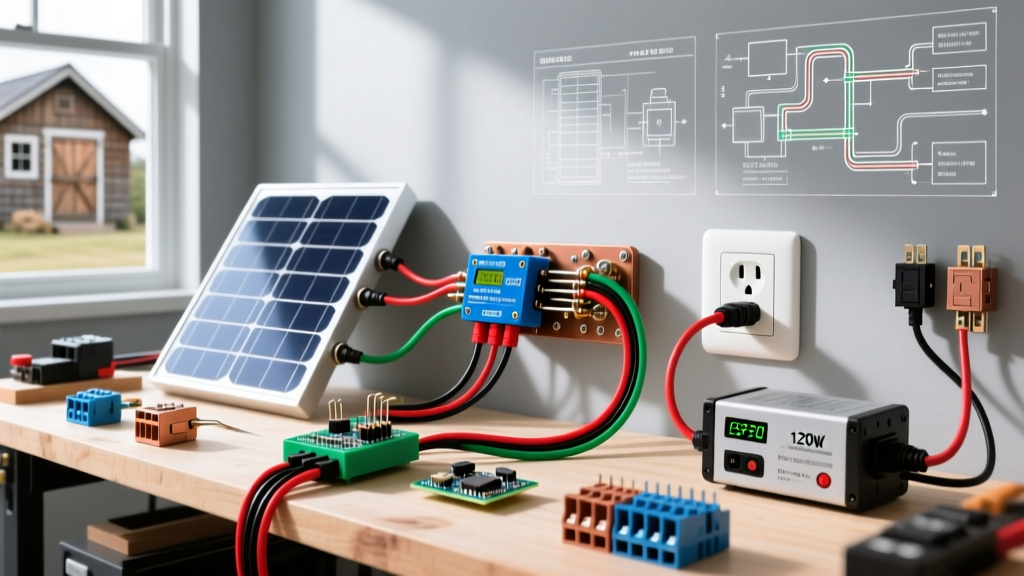
The most frequent use case for a solar powered electrical outlet is providing standard 120V AC power to an off-grid outbuilding. This requires converting DC battery power to AC via an inverter, routing it through a subpanel or direct breaker, and terminating at a standard NEMA 5-15R receptacle.
Sizing the Inverter and Wire Gauge
For a standard 15A receptacle circuit, your inverter must be capable of sustaining at least 1,800W continuous output. A highly reliable choice in 2026 is the Victron Energy Phoenix 12/1600 (12V DC to 120V AC, 1600VA), which retails for approximately $450. It features a pure sine wave output, which is mandatory for modern electronics and GFCI receptacles.
- Battery to Inverter Wiring: For a 12V system pulling up to 130A at peak load, you must use 1/0 AWG or 2/0 AWG stranded copper welding cable for runs under 5 feet. Keep this DC run as short as physically possible to minimize voltage drop.
- Inverter to Outlet Wiring (AC Side):strong> From the inverter's AC output, route 12 AWG THHN copper wire through 1/2-inch EMT conduit. While 14 AWG is technically permitted for 15A circuits under NEC Article 310, 12 AWG is strongly recommended for solar outbuildings to mitigate voltage drop over longer trench runs.
Step-by-Step AC Wiring Flow
- Install the DC Disconnect: Mount a 150A Class-T fuse (e.g., Bussmann ANN-150) on the positive battery cable within 7 inches of the battery terminal, as mandated by NEC 690.101.
- Route the AC Output: Connect the inverter's Line, Neutral, and Ground to a 15A single-pole breaker in a small 2-space load center (like a Square D QO24L70).
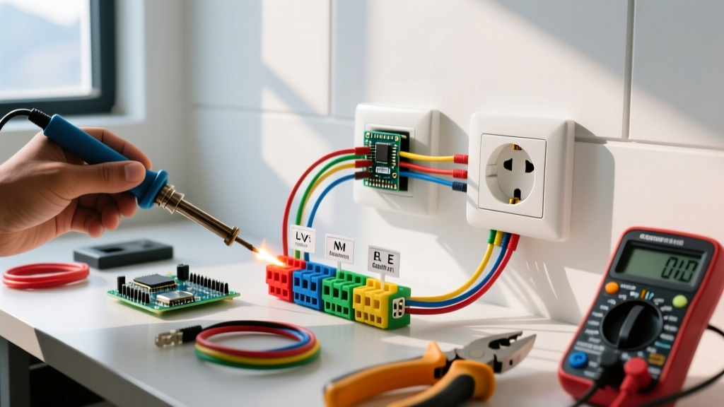
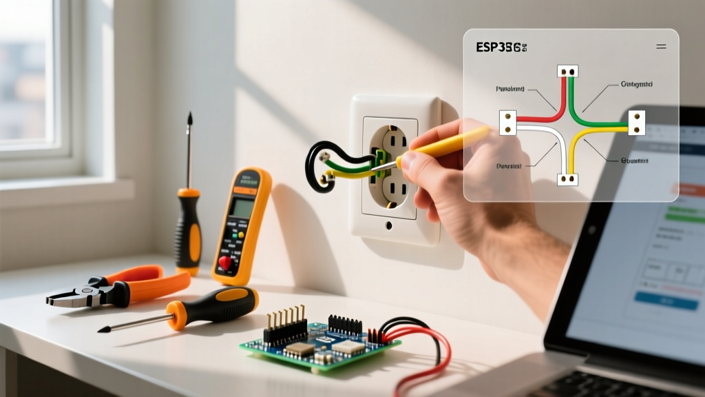
- Terminate the Receptacle: At the outlet box, strip 3/4 inch of insulation. Connect the black (hot) wire to the brass terminal, the white (neutral) to the silver terminal, and the bare copper to the green ground screw. Use a commercial-grade Tamper-Resistant (TR) receptacle, such as the Leviton 5262-T, which offers superior clamping force for $3.50 per unit compared to standard residential builder-grade outlets.
Scenario 2: Direct 12V DC Solar Outlets (RV and Off-Grid Cabins)
If your goal is to power 12V LED lighting, USB-C PD charging hubs, or 12V compressor fridges (like the Dometic CFX3 series), bypassing the inverter entirely saves 10% to 15% in conversion energy losses. In this scenario, the solar powered electrical outlet is a specialized DC receptacle wired directly to the MPPT charge controller's load terminals or a dedicated DC fuse block.
Specialized DC Receptacles and Fusing
Standard AC outlets cannot be used for DC power due to differing polarization and safety standards. Instead, utilize marine-grade 12V sockets. The Blue Sea Systems 900412 WeatherDeck (approx. $18) is an industry standard, featuring a waterproof cap and robust internal contacts rated for 15A at 12V DC.
- Wire Sizing for DC: Voltage drop is the enemy of 12V DC circuits. A 10A load on a 14 AWG wire over just 15 feet will result in a 5% voltage drop, potentially causing low-voltage disconnects on sensitive appliances. Always use a minimum of 10 AWG stranded marine wire for 12V outlet runs up to 20 feet.
- Fusing: Install an inline ATO (Automotive) fuse holder on the positive wire within 7 inches of the DC distribution bus. For a 12V receptacle, a 15A ATO blade fuse is the standard protection threshold.
Comparison Matrix: AC Inverter vs. Direct DC Wiring
| Feature | 120V AC Inverter-Fed Outlet | 12V DC Direct-Wired Outlet |
|---|---|---|
| Primary Use Case | Power tools, laptops, standard AC appliances | 12V fridges, USB charging, marine LED lighting |
| Receptacle Type | NEMA 5-15R (Standard 3-prong TR) | Hella/ISO standard or Cigarette-style Marine Socket |
| Wire Gauge (15ft run) | 12 AWG THHN (AC) | 10 AWG Stranded Marine (DC) |
| System Efficiency | 85% - 93% (Inverter conversion losses) | 99% (Minimal resistive line loss) |
| Estimated Material Cost | $450+ (Inverter) + $25 (Wire/Breaker) | $18 (Socket) + $15 (Fuse block/Wire) |
Crucial Code Compliance: Grounding and Source Identification
When wiring solar-powered receptacles, electricians frequently run afoul of NEC Article 690. The National Fire Protection Association (NFPA) outlines strict rules for systems that operate independently of the grid or as hybrid backup systems. You can review the complete NFPA 70 National Electrical Code documentation for local adoption cycles.
NEC 690.56 Identification of Power Sources: Any building or structure with both a utility service and a solar photovoltaic system must feature a permanent plaque or directory at the main service disconnect. This plaque must clearly identify the location of all power sources, including the solar inverter and battery bank disconnects, to protect first responders.
Furthermore, if your solar powered electrical outlet is installed in a damp location (such as an uninsulated shed or outdoor pavilion), NEC Article 406.3(D) requires the receptacle to be GFCI protected. If you are off-grid with no utility ground rod, you must install a dedicated grounding electrode system (typically two 8-foot copper-clad ground rods spaced 6 feet apart, bonded with 6 AWG bare copper) connected to the inverter's chassis ground lug to ensure the GFCI can detect ground faults accurately.
Troubleshooting Common Solar Outlet Failures
Even with meticulous wiring, solar-fed outlets exhibit unique failure modes not seen in standard grid-tied circuits. Here is how to diagnose the most frequent issues encountered in the field:
1. GFCI Nuisance Tripping on AC Outlets
The Symptom: The GFCI receptacle trips immediately when an appliance is plugged in, or randomly with no load attached.
The Root Cause: You are likely using a Modified Sine Wave (MSW) inverter. MSW inverters produce a stepped, square-wave approximation of AC power. This high-frequency harmonic distortion creates electrical 'noise' that leaks to the ground wire, which the sensitive internal toroidal coil of a GFCI receptacle misinterprets as a ground fault.
The Fix: Upgrade to a Pure Sine Wave (PSW) inverter. Alternatively, if the load does not strictly require GFCI protection by local code (e.g., a dry, finished interior wall in some jurisdictions), replace the GFCI with a standard TR receptacle.
2. Severe Voltage Sag on 12V DC Outlets
The Symptom: A 12V compressor fridge clicks rapidly and fails to start, even though the battery monitor reads 13.2V.
The Root Cause: Undersized wiring or poor crimp connections at the DC receptacle. Compressor fridges can draw 15A+ during startup surges. If the wire is too thin, or if the spade connectors on the back of the 12V socket are loose, the voltage at the receptacle drops below 10.5V under load, triggering the fridge's low-voltage protection.
The Fix: Replace push-fit spade connectors with fully crimped and heat-shrink-sealed ring terminals. Verify voltage directly at the back of the receptacle terminals while the appliance is attempting to start. The Department of Energy provides excellent baseline guidelines on solar energy basics and system sizing to help calculate these initial surge loads.
3. Inverter Idle Drain Depleting the Battery Bank
The Symptom: The off-grid shed battery bank is dead by morning, despite no appliances being left on.
The Root Cause: Inverters consume power simply by being turned on, known as 'idle current draw.' A large 3000W inverter can draw 1.5A to 2.5A continuously from a 12V battery just to keep its internal capacitors charged and control board active. Over 24 hours, this consumes up to 60Ah of battery capacity.
The Fix: Wire a heavy-duty DC solenoid or a remote inverter on/off switch (like the Victron VE.Net remote panel) to the outlet circuit, allowing the user to physically cut DC power to the inverter when the solar powered electrical outlet is not in active use.
Final Thoughts on Solar Receptacle Safety
Wiring a solar powered electrical outlet bridges the gap between renewable energy generation and practical, everyday utility. By respecting the physics of DC voltage drop, investing in pure sine wave inversion, and strictly following NEC identification and grounding mandates, you ensure your off-grid or backup circuits are as safe and reliable as any utility-fed grid. Always consult with a licensed electrician and review the latest Solar Energy Industries Association (SEIA) safety protocols before energizing a new photovoltaic microgrid.