
The Critical Intersection of Outdoor Wiring and NEC Compliance
Learning how to install an exterior electrical outlet goes far beyond simply connecting black, white, and bare copper wires. Outdoor environments subject electrical components to extreme temperature cycling, UV radiation, moisture ingress, and physical impact. Consequently, the National Electrical Code (NEC) enforces stringent requirements for exterior receptacles to prevent electrocution and electrical fires. According to the U.S. Consumer Product Safety Commission (CPSC), Ground Fault Circuit Interrupter (GFCI) technology has reduced residential electrocutions by over 80% since its widespread adoption, but only when installed and maintained to code.
This comprehensive safety guide details the exact materials, code requirements, and step-by-step procedures required to install a weatherproof, NEC-compliant exterior outlet in 2026. We will bypass generic advice and focus on the specific torque values, sealing compounds, and failure-mode mitigations that professional electricians use daily.
NEC Code Compliance Matrix for Exterior Receptacles
Before purchasing materials, you must understand the governing codes. The NEC 2023 edition (which remains the active baseline for most jurisdictions in 2026) outlines specific mandates for outdoor receptacles. Below is a breakdown of the critical articles you must satisfy.
| NEC Article | Requirement | Practical Application |
|---|---|---|
| 210.8(A)(3) | GFCI Protection | All 15A and 20A, 125V exterior receptacles must have ground-fault protection for personnel. |
| 406.9(A) | Weather-Resistant (WR) Rating | Receptacles must be listed as 'Weather-Resistant' (marked WR), featuring UV-stabilized plastics and corrosion-resistant metals. |
| 406.9(B) | Extra-Duty In-Use Covers | An 'in-use' (extra-duty) weatherproof cover must be installed, allowing the cover to close while a cord is plugged in. |
| 110.14(D) | Terminal Torque | All terminating screws must be tightened to the manufacturer's specified torque (typically 14 in-lbs for 15A/20A devices). |
Required Materials and Tools
Do not substitute indoor-rated components for outdoor use. Standard PVC and nylon will become brittle and crack after 12 to 18 months of direct UV exposure. Procure the following specific items to ensure longevity and code compliance:
- Receptacle: Leviton 5262-CW2 (15A) or 5362-CW2 (20A) Weather-Resistant GFCI. (Cost: ~$24 - $28). The 'CW2' designation indicates the white, weather-resistant model.
- Enclosure: Carlon B618R-UPC (Non-metallic single-gang) or Bell PVB10100GY (Cast aluminum for masonry). (Cost: ~$8 - $22).
- Cover: Taymac MM540C Extra-Duty In-Use Cover. (Cost: ~$19). Features a deep profile for bulky transformer plugs.
- Sealant: Gardner Bender GBP-1210 Duct Seal Compound and 100% silicone caulk.
- Tools: Klein Tools NCVT-4IR (Non-contact voltage tester with IR thermometer), Wiha insulated torque screwdriver, wire strippers, and a cable ripper.
Step-by-Step Installation Procedure
Step 1: Power Verification and Circuit Identification
Shut off the breaker supplying the circuit. Do not rely solely on a standard non-contact voltage tester, as phantom voltages can cause false readings. Use the Klein NCVT-4IR to verify the absence of voltage at the nearest interior outlet on the same circuit. Once confirmed dead, use the IR thermometer feature to check the breaker panel for any anomalous heat signatures on adjacent breakers before beginning work.
Step 2: Mounting the Weatherproof Box
If mounting to wood siding, apply a continuous bead of 100% exterior-grade silicone to the back flange of the Carlon PVC box before driving the mounting screws. This prevents capillary action from drawing rain behind your siding. If mounting to brick or stucco, use a cast aluminum box with integral mounting flanges and secure it using Tapcon masonry screws. Never use standard drywall screws for exterior masonry mounting; they will rust and fail within two years.
Step 3: Wiring the WR GFCI Receptacle
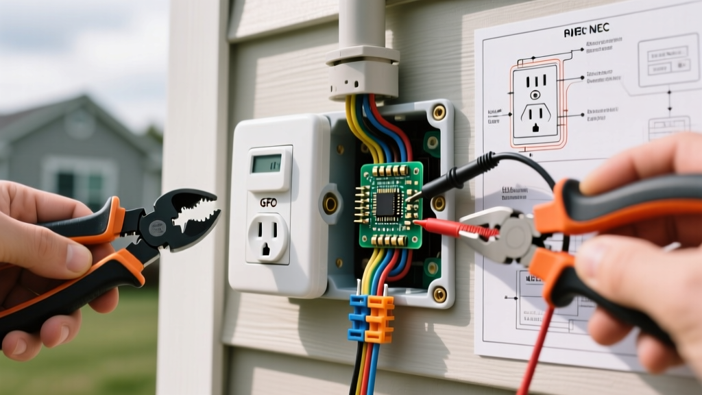
Strip the wire insulation to the exact length indicated by the strip gauge on the back of the Leviton GFCI (usually 5/8 inch). Identify the LINE versus LOAD terminals. The power from the panel connects to the LINE terminals. The LOAD terminals are only used if you are protecting a downstream receptacle. For a single exterior outlet, cap the LOAD wires with wire nuts.
Critical Safety Note: The National Fire Protection Association (NFPA) emphasizes that loose connections are a leading cause of electrical fires. Use your torque screwdriver set to 14 in-lbs (or the exact spec printed on the Leviton device) to secure the terminal screws. Hand-tightening is no longer code-compliant under NEC 110.14(D).
Step 4: Sealing and Weatherproofing
Before pushing the GFCI into the box, pack any open conduit knockouts or cable entry points with Gardner Bender duct seal. This putty-like compound blocks moisture, insects, and cold drafts from entering the wall cavity. Attach the Leviton receptacle, ensuring the rubber gasket provided with the WR device sits flush against the box rim. Finally, mount the Taymac in-use cover, applying a thin bead of silicone across the top edge of the cover flange to shed water, leaving the bottom edge unsealed to allow condensation to weep out.
Common Failure Modes and Edge Cases
Even with perfect installation, exterior outlets face unique environmental stresses. Understanding these failure modes will save you from endless troubleshooting callbacks.
1. Condensation-Induced Nuisance Tripping
The Problem: Warm, humid summer air enters the outlet box through the in-use cover gaps. When the temperature drops at night, the moisture condenses on the cold metal terminals of the GFCI, creating a micro-leakage path to ground that trips the device.
The Fix: Apply a thin layer of dielectric grease to the non-conductive plastic housing and the inside of the cover (avoiding the actual terminal contacts and plug faces). Ensure the weep holes at the bottom of the in-use cover are not clogged with paint or debris.
2. Neutral-to-Ground Faults from Moisture Ingress
The Problem: If water bypasses the cover and bridges the neutral bus and the ground wire inside the box, the GFCI will trip immediately, even with no load connected.
The Fix: This is almost always caused by failing to use duct seal on the conduit hubs or using a cracked, non-WR rated receptacle. Replace the device with a verified WR model and re-seal all conduit entries.
3. UV Degradation of the Cover Hinge
The Problem: Cheap, big-box store in-use covers use standard polycarbonate hinges that snap off after one season of direct sunlight.
The Fix: Always purchase covers explicitly marked as UV-stabilized or made from die-cast aluminum, like the Taymac MM540C or Bell Elite series.
Frequently Asked Questions (FAQ)
Does an exterior outlet require a dedicated circuit?
No. The NEC does not require a dedicated circuit for a standard exterior receptacle. It can be tapped from an existing 15A or 20A interior branch circuit, provided the total calculated load does not exceed the breaker rating. However, it must be protected by a GFCI device, either at the receptacle itself or at the upstream breaker.
Can I use a standard indoor GFCI if I put an in-use cover over it?
No. This is a direct violation of NEC 406.9(A). Standard indoor GFCIs are not tested for extreme temperature cycling or UV exposure. The internal electronics can degrade rapidly when subjected to the micro-climates generated inside an outdoor enclosure. You must use a device stamped with the 'WR' (Weather-Resistant) logo.
What is the required height for an exterior outlet?
The NEC does not specify a minimum or maximum mounting height for general-purpose exterior receptacles. However, for accessibility and practical use (such as plugging in holiday lights or power tools), the industry standard is to mount the center of the receptacle box between 18 inches and 24 inches above the final grade. If installed in a garage or breezeway, 48 inches is standard. Always ensure the in-use cover can fully open without hitting the ground or landscaping.
Final Safety Verification
After completing the installation and restoring power, use a standard 3-light receptacle tester equipped with a GFCI test button. Plug it into the new exterior outlet and press the test button. The GFCI should immediately click and cut power to the tester. Reset the device. For further reading on outdoor electrical safety and the importance of ground-fault protection, consult the Electrical Safety Foundation International (ESFI) resources on GFCI maintenance and testing. By adhering strictly to these material specifications and NEC guidelines, your exterior outlet will provide safe, reliable power for decades.