
Introduction to 7-Way RV Blade Connectors and Safety Standards
When towing heavy loads, RVs, or utility trailers, the electrical connection between your tow vehicle and the trailer is a critical safety system. Understanding the correct wiring diagram for a 7-way trailer plug is not just about making the lights work; it is about adhering to strict Department of Transportation (DOT) regulations and SAE International standards. As of 2026, with the rise of heavy-duty electric tow vehicles like the F-150 Lightning and Rivian R1T, the demand on the 12V auxiliary and electric brake circuits has increased significantly, making proper wire gauge sizing and circuit protection more vital than ever.
This comprehensive safety and code compliance guide breaks down the SAE J286 standard pinout, mandatory wire gauges, voltage drop mitigation, and termination best practices to ensure your trailer wiring is safe, legal, and reliable.
The SAE J286 Pinout Standard vs. Aftermarket Reality
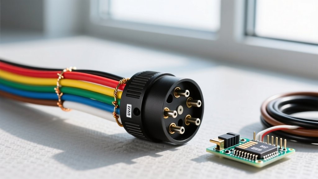
The 7-way RV blade connector (often called the 7-pin trailer plug) is governed by the SAE J286 standard. This standard dictates the physical layout and the intended function of each pin. However, a major point of failure in DIY trailer wiring is the assumption that wire jacket colors always match the SAE standard. According to Penn State Extension's agricultural safety guidelines, aftermarket wiring harnesses frequently deviate from standard color codes, leading to dangerous cross-wiring and blown vehicle modules.
Official 7-Way Pinout and Wire Sizing Matrix
| Pin Position | Function | SAE Standard Wire Color | Minimum AWG (Up to 25ft) | Circuit Protection |
|---|---|---|---|---|
| 1 (Center) | 12V Auxiliary / Battery Charge | Black | 10 AWG | 30A - 40A Auto-Reset Breaker |
| 2 (Top Left) | Tail / Running Lights | Brown | 12 AWG | 15A Fuse / Vehicle Module |
| 3 (Bottom Left) | Left Turn / Stop | Red | 12 AWG | 15A Fuse / Vehicle Module |
| 4 (Bottom Center) | Electric Trailer Brakes | Blue | 10 AWG | 30A Auto-Reset Breaker |
| 5 (Bottom Right) | Right Turn / Stop | Green | 12 AWG | 15A Fuse / Vehicle Module |
| 6 (Top Right) | Reverse Lights / Aux | Yellow | 14 AWG | 10A Fuse |
| 7 (Top Center) | Ground (Chassis) | White | 10 AWG (or 8 AWG) | N/A (Direct to Battery Neg) |
Critical Safety Warning: Never trust the color of the wire jacket on pre-assembled aftermarket pigtails. Always use a digital multimeter to continuity-test each pin against the wire ends before soldering or crimping. A swapped brake and auxiliary wire can send 12V continuous power to your trailer's brake magnets, causing them to overheat and catch fire while driving.
Wire Gauge Sizing and Voltage Drop Mitigation
One of the most common code violations in trailer wiring is undersizing the wires for the electric brake and 12V auxiliary circuits. The National Electrical Code (NEC) principles regarding voltage drop apply heavily to DC automotive circuits. Electric trailer brakes can draw between 12A and 15A per axle. On a tandem-axle trailer, the total draw can exceed 30A during a panic stop.
The Voltage Drop Problem
If you use 14 AWG wire for the blue electric brake circuit over a 25-foot run (50 feet total circuit length including the ground), the resistance will cause a significant voltage drop. Brake controllers require precise voltage modulation to apply the correct braking force. If the voltage at the brake magnets drops below 10V due to undersized wiring, the trailer brakes will engage weakly, leading to jackknifing or extended stopping distances.
- 14 AWG Wire: Drops approx. 2.6V at 15A over 50ft. (Unacceptable for brakes)
- 12 AWG Wire: Drops approx. 1.6V at 15A over 50ft. (Marginal for heavy loads)
- 10 AWG Wire: Drops approx. 1.0V at 15A over 50ft. (SAE Recommended for brakes and 12V aux)
For the white ground wire, upgrading to 8 AWG is highly recommended for large RVs to ensure the return path can handle the combined amperage of the running lights, brake lights, and auxiliary charging without creating a ground loop.
Circuit Protection: FMVSS 108 and Breaker Selection
Federal Motor Vehicle Safety Standard (FMVSS) 108 governs all lighting and reflective devices on trailers, mandating that electrical systems must be protected against short circuits and overloads. You can review the specific federal lighting regulations via the Electronic Code of Federal Regulations (eCFR) Title 49.
Auto-Resetting PTC Breakers vs. Standard Fuses
For the 12V Auxiliary (Black) and Electric Brake (Blue) circuits, you must use auto-resetting PTC (Positive Temperature Coefficient) circuit breakers, not standard blade fuses. If a trailer brake wire chafes against the frame and shorts out, a standard fuse will blow, leaving you with zero trailer brakes for the remainder of your trip. An auto-resetting breaker (such as the Bussmann CB185-40 40-Amp model) will trip, cut the power, cool down, and reset itself in seconds, allowing the brake controller to continue functioning during an intermittent short.
Installation Rule: The circuit breaker for the 12V auxiliary feed must be installed within 18 inches of the tow vehicle's battery positive terminal to protect the entire length of the wire running to the rear bumper.
Termination Best Practices for Environmental Sealing
The environment underneath a vehicle is brutal. Road salt, UV exposure, and high-pressure car washes will destroy cheap electrical connections. To meet SAE International durability expectations, follow these termination protocols:
- Use Heat-Shrink Ring Terminals: Discard the cheap vinyl-insulated crimp terminals. Use adhesive-lined, marine-grade heat shrink ring terminals (e.g., 3M Highland or Molex). When heated, the inner adhesive melts and seals the wire strands against moisture and corrosion.
- Apply Anti-Oxidant Compound: Before tightening the ring terminals to the brass screws inside the 7-way plug, apply a small amount of NO-OX-ID A-Special or a high-quality dielectric grease to the threads and terminal faces. This prevents galvanic corrosion between the copper wire and brass terminal.
- Torque Specifications: Tighten the terminal screws to approximately 15-20 in-lbs. Overtightening will strip the soft brass threads or snap the screw head; undertightening will cause electrical arcing, which melts the plastic plug housing and creates a fire hazard.
- Strain Relief: Ensure the rubber cord grip at the base of the 7-way plug is tightened securely around the outer jacket of the wire bundle, not just the individual wires. This prevents the tension of the cable from pulling the ring terminals off the screws.
Troubleshooting Ground Faults and Backfeed Issues
Over 70% of trailer lighting issues are not caused by bad bulbs or broken wires, but by inadequate grounding. The 7-way plug relies on Pin 7 (White) to complete the circuit back to the tow vehicle's battery.
The 'Frame Ground' Fallacy
Many DIYers terminate the white ground wire to the trailer's steel frame near the tongue and assume the vehicle's hitch ball will complete the ground path back to the truck. This is a severe safety violation. Hitch balls are often painted, coated in grease, or rusted, creating high resistance. Furthermore, relying on the hitch for grounding can cause 'backfeed,' where 12V current travels through the trailer's steel frame and into the truck's chassis, potentially frying the truck's CAN-bus system or body control module (BCM).
The Fix: Run a dedicated 10 AWG or 8 AWG white ground wire all the way from the 7-way plug directly to the trailer's main battery negative terminal or a dedicated, bare-metal grounding lug bolted directly to the trailer's main chassis beam with a star washer.
Frequently Asked Questions (FAQ)
Can I use a 4-way flat to 7-way adapter for a heavy RV?
No. A 4-way flat connector only supports running lights, left turn, and right turn. It lacks the dedicated pins for electric brakes and 12V auxiliary power. Using an adapter for a heavy RV means you will have no trailer brakes, which is illegal in all 50 states for trailers over 3,000 lbs GVWR and highly dangerous.
What happens if I wire the 12V auxiliary to the brake controller output?
If you swap the Blue (Brakes) and Black (12V Aux) wires, your trailer's breakaway battery will receive a continuous 12V charge from the truck, but your brake controller will send pulsing 12V signals to your trailer's interior 12V appliances and battery, likely destroying your RV's power converter and battery management system.
How often should I inspect the 7-way plug for corrosion?
For daily drivers and commercial haulers, inspect and re-apply dielectric grease every 6 months. For seasonal RV owners, inspect the plug and socket in the spring before your first trip. If you see green verdigris (copper oxidation) on the pins, clean them with electrical contact cleaner and a brass wire brush.