
Understanding the South Africa Electrical Outlet Landscape
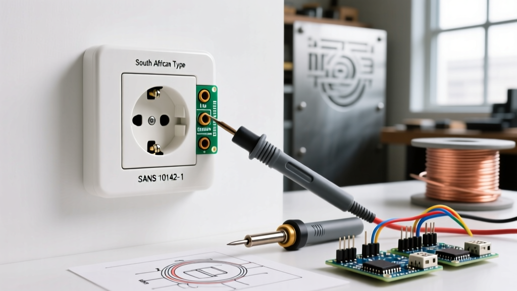
When working with electrical infrastructure in Southern Africa, understanding the specific standards governing the South Africa electrical outlet is critical for safety and compliance. As of 2026, the South African market operates on a 230V/50Hz AC supply. While the newer SANS 164-2 (Type N) standard is gradually being phased into new builds, the legacy SANS 164-1 (Type M)—characterized by its three large round pins (15A) or small round pins (5A)—remains the most ubiquitous receptacle in residential and commercial environments.
According to the International Electrotechnical Commission (IEC), Type M plugs (based on the BS 546 standard) are heavily utilized in South Africa, India, and neighboring regions. Inspecting and testing these outlets requires strict adherence to the SANS 10142-1 standard (The Wiring of Premises), which dictates rigorous parameters for earth continuity, polarity, and fault loop impedance. This guide provides a comprehensive, professional-grade inspection and testing protocol for electricians and advanced DIYers.
Pre-Inspection Safety & Tool Requirements
Before removing any faceplates or inserting test probes, you must establish a safe working environment. The South African Department of Employment and Labour enforces strict Occupational Health and Safety (OHS) regulations regarding live electrical work. Always assume a circuit is live until proven dead using a verified voltage indicator.
Essential Testing Equipment
- Multifunction Installation Tester: Devices like the Metrel MI 3155 EurotestXD or Kyoritsu KEW 6516 are mandatory for SANS 10142-1 compliance. These units cost between R25,000 and R35,000 ZAR ($1,300 - $1,800 USD) and automate earth loop, RCD, and polarity tests.
- True-RMS Digital Multimeter: A Fluke 87V or equivalent for verifying point-to-point voltages and detecting ghost voltages.
- Calibrated Voltage Indicator (VI): For dead-circuit verification before visual inspections.
- Torque Screwdriver: Calibrated to 1.2 Nm - 1.5 Nm for securing 2.5mm² stranded copper conductors.
Phase 1: Visual & Mechanical Inspection Protocol
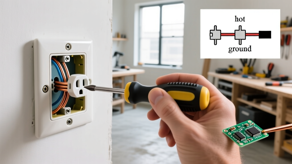
A significant percentage of electrical fires originate from degraded receptacles. Before applying power, isolate the circuit at the distribution board (DB) and perform a thorough visual inspection.
- Faceplate & Shutter Integrity: Inspect the Bakelite or polycarbonate faceplate for micro-fractures, UV degradation, or scorch marks. The mechanical safety shutters must operate smoothly; if a shutter is jammed, users may force plugs, damaging the internal phosphor bronze contacts.
- SABS Certification Mark: Verify the presence of the South African Bureau of Standards (SABS) approval mark on the rear of the outlet. Counterfeit outlets often use cheap brass or steel internal contacts instead of phosphor bronze, leading to high resistance, thermal runaway, and eventual melting under a 15A load.
- Terminal Torque Check: If the outlet was recently installed, verify that the terminal screws are tightened to exactly 1.2 Nm. Under-torqued 2.5mm² conductors will arc under heavy inductive loads (like geysers or pool pumps), while over-torquing can shear the stranded copper wires, reducing the effective cross-sectional area.
- Pin Dimension Verification: For the 15A Type M outlet, the earth pin aperture must accommodate a 8.71mm diameter pin, while the Line and Neutral apertures accept 7.05mm pins. Worn apertures indicate the outlet has exceeded its mechanical lifecycle and must be replaced.
Phase 2: Live Voltage & Polarity Testing Matrix
Once the visual inspection is complete and the faceplate is securely reinstalled, restore power to the circuit. Use your multifunction tester or True-RMS multimeter to record the following parameters. SANS 10142-1 mandates that the supply voltage must remain within +10% and -15% of the nominal 230V (i.e., between 195.5V and 253V).
| Test Parameter | Expected Reading | SANS 10142-1 Tolerance | Common Fault Indication |
|---|---|---|---|
| Line to Neutral (L-N) | 230V AC | +10% / -15% | Open neutral, high resistance joint, or overloaded transformer tap |
| Line to Earth (L-E) | 230V AC | +10% / -15% | Open earth, missing ground rod, or broken earth conductor |
| Neutral to Earth (N-E) | < 2.0V AC | Ideally < 1.0V | Bootleg ground (N-E bonded at outlet), overloaded neutral, or shared neutral fault |
| Polarity Check | Pass (L to Line) | Must be correct | Reversed Line/Neutral wiring at the DB or outlet terminals |
Expert Warning: A Neutral-to-Earth voltage reading above 3V under load is a critical red flag. It indicates severe neutral conductor degradation or an illegal neutral-earth bond downstream of the main distribution board, which can cause dangerous circulating currents on the earth wire.
Phase 3: Earth Loop Impedance (Zs) & PFC Testing
Voltage testing only tells half the story. To ensure that a circuit breaker will actually trip during a dead-short fault, you must measure the Earth Fault Loop Impedance (Zs). This measures the total resistance of the fault path from the transformer, through the Line conductor, through the fault, and back via the Earth conductor.
Calculating Zs Limits
The maximum permissible Zs is calculated using the formula: Zs = Uo / Ia, where Uo is the nominal voltage (230V) and Ia is the current required to trip the protective device within 0.4 seconds.
- For a 16A Type C MCB: Ia is typically 160A (10 x In). Therefore, max Zs = 230 / 160 = 1.44 Ω.
- For a 20A Type C MCB: Ia is 200A. Therefore, max Zs = 230 / 200 = 1.15 Ω.
If your multifunction tester records a Zs value higher than these thresholds, the breaker will not trip fast enough to prevent a fire or lethal shock. You must investigate the earth path, check for corroded main bonding conductors, or upgrade the cable size.
Prospective Fault Current (PFC)
Alongside Zs, test the PFC at the outlet. In a standard residential setup, the PFC at the furthest outlet should typically read between 1.5 kA and 3 kA. Ensure that the MCB's breaking capacity (usually 6 kA for standard residential SANS-compliant breakers) exceeds the measured PFC.
Troubleshooting Common SANS 164-1 Outlet Failures
When tests fail, systematic troubleshooting is required. Here are the most frequent edge cases encountered in South African installations:
- High Earth Loop Impedance (Zs > 1.44 Ω): Often caused by the use of undersized earth wires in older conduit installations, or corrosion at the main earth bar in the DB. Check the main equipotential bonding to the municipal water pipe and ground spike.
- Reversed Polarity with Correct L-N Voltage: The outlet will power appliances, but the internal switch on the appliance will only isolate the neutral, leaving the heating element or motor live. This is a frequent cause of fatal shocks during appliance maintenance. Trace the wiring back to the DB to find where the Line and Neutral were swapped.
- RCD (Earth Leakage) Nuisance Tripping: If the 30mA earth leakage breaker trips when plugging in a device, test the RCD trip times. At 1x IΔn (30mA), it must trip in <40ms. At 0.5x IΔn (15mA), it must not trip. If it fails, the RCD module is faulty, or there is cumulative earth leakage from multiple appliances on the same circuit exceeding 10mA.
Regulatory Compliance & The CoC Process
In South Africa, any modification, addition, or repair to an electrical installation requires an updated Certificate of Compliance (CoC) issued by a registered Installation Electrician (IE) or Master Installation Electrician (MIE). Testing a South Africa electrical outlet is not merely a diagnostic exercise; it is a legal verification process.
When conducting a CoC inspection, the testing data for every single outlet—including Zs, PFC, and RCD trip times—must be logged on the official SANS 10142-1 Test Report schedule. Failing to document these specific readings, or using non-calibrated testing equipment, invalidates the CoC and exposes the property owner to severe liability under the OHS Act in the event of an electrical fire or injury.
By adhering to this rigorous inspection and testing matrix, electrical professionals ensure that South Africa's legacy Type M infrastructure remains safe, reliable, and fully compliant with modern 2026 safety standards.