
The Code Landscape for Exterior Receptacles
Adding an outdoor electrical outlet is one of the highest-ROI DIY electrical projects you can undertake, enabling everything from power tool usage and holiday lighting to EV trickle charging. However, exterior environments subject wiring to moisture, UV degradation, and extreme temperature fluctuations. The National Electrical Code (NEC) enforces strict guidelines for exterior installations to prevent ground faults and electrical fires.
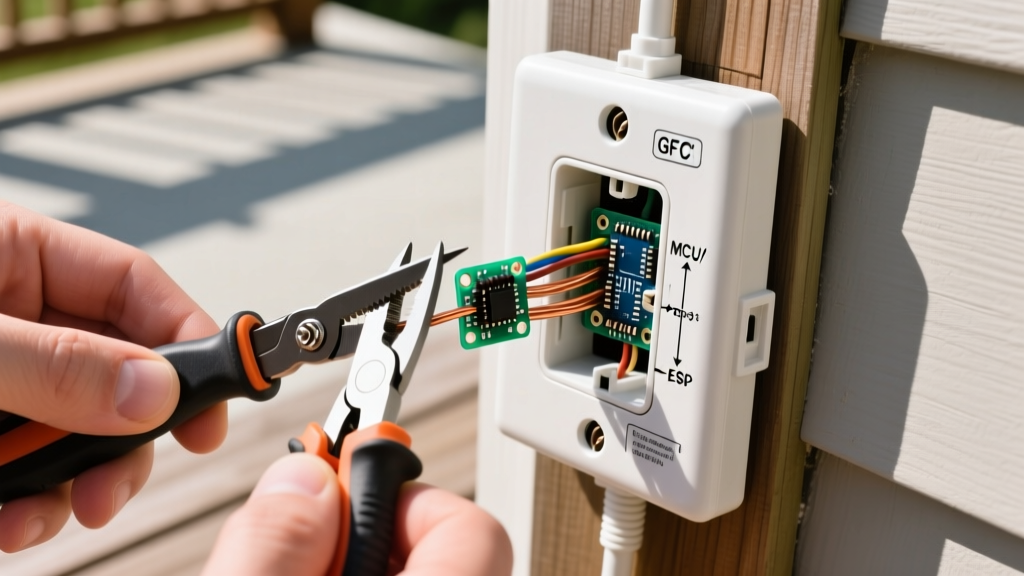
According to the National Fire Protection Association (NFPA) NEC Code Directory, all outdoor receptacles must be GFCI (Ground Fault Circuit Interrupter) protected, weather-resistant (WR), and tamper-resistant (TR). Furthermore, NEC 406.9(B)(1) mandates the use of extra-duty, weatherproof while-in-use covers for all damp and wet locations. Failing to use a while-in-use cover is the most common code violation DIYers make, leading to premature GFCI failure due to internal condensation.
Expert Note: Never use standard indoor NM-B (Romex) cable for exterior runs, even if it is routed inside PVC conduit. NM-B is not rated for damp locations. You must use UF-B (Underground Feeder) cable, which features a solid, moisture-resistant PVC jacket encasing the individual conductors.
Materials & Tool Matrix
Selecting the correct, code-compliant components is critical. Below is the exact bill of materials required for a standard through-wall installation from an interior 20A circuit.
| Component | Recommended Model | Est. Cost | Purpose & Code Requirement |
|---|---|---|---|
| WR/TR GFCI Receptacle | Leviton GFNT2-W (20A) | $22.50 | Provides shock protection; WR coating resists corrosion. |
| Weatherproof Box | Carlon B618RR (18 cu in) | $11.00 | Non-metallic, round, deep box for exterior mounting. |
| While-In-Use Cover | TayMac MM410C Extra Duty | $18.00 | Allows cords to be plugged in with the cover closed. |
| Outdoor Cable | Southwire 12/2 UF-B | $1.10/ft | Moisture/UV rated; 12 AWG required for 20A circuits. |
| Sealant | GE Silicone II Clear | $8.50 | Waterproofs the box-to-siding interface. |
| Torque Screwdriver | Klein Tools 70250 | $45.00 | Ensures terminal screws meet manufacturer torque specs. |
Phase 1: Circuit Selection and Interior Prep
Before drilling any holes, you must identify a suitable interior circuit. Per NEC 210.52(E), outdoor receptacles must be on a 20-ampere branch circuit. While you can tap into an existing indoor 20A circuit (like a kitchen or garage circuit), you must ensure the circuit will not be overloaded by your intended outdoor loads.
- Verify the Circuit: Use a non-contact voltage tester (like the Klein NCVT-3) and a plug-in circuit analyzer to confirm the interior outlet is on a 20A breaker and has a proper ground.
- Shut Off Power: Turn off the 20A breaker at the main panel. Apply a piece of painter's tape over the breaker to prevent accidental re-engagement while you work.
- Box Fill Calculation (Crucial Step): The Carlon B618RR has an 18-cubic-inch capacity. Under NEC 314.16, 12 AWG wires require 2.25 cubic inches of fill per wire. One incoming UF-B cable (2 current-carrying wires + 1 ground), plus the internal clamp, plus the GFCI device (counts as 2 wires), equals exactly 18 cubic inches. If you plan to daisy-chain another outlet from this box (using the LOAD terminals), you must upgrade to a 22-cubic-inch box like the Carlon B620RR to avoid a box-fill violation.
Phase 2: Drilling and Exterior Box Mounting
The physical penetration through the building envelope requires careful waterproofing to prevent wood rot and insect intrusion.
- Drill the Rim Joist: From the exterior, locate a bay that aligns with the interior circuit. Use a 3/4-inch spade bit or auger bit. Pro Tip: Angle the drill bit slightly downward (about 5 degrees) toward the outside. This creates a weep slope, ensuring any condensation or driving rain drains outward rather than pooling inside the wall cavity.
- Feed the UF-B Cable: Strip the outer gray sheath of the UF-B cable using a specialized UF-B stripping tool or a very careful utility knife, being meticulous not to nick the copper conductors. Push the cable through the hole, leaving exactly 8 inches of slack protruding from the exterior wall.
- Mount the Exterior Box: Thread the UF-B through the rear hub of the Carlon B618RR. Apply a thick, continuous bead of GE Silicone II around the entire back perimeter of the box. Press it firmly against the siding or stucco and secure it using four #10 x 2-inch stainless steel exterior screws. The silicone should squeeze out slightly, creating a watertight gasket.
Phase 3: Wiring the WR GFCI Receptacle
Wiring a GFCI requires strict attention to the LINE and LOAD terminals. The U.S. Consumer Product Safety Commission (CPSC) notes that reversed line/load wiring is a primary cause of GFCI failure to protect downstream devices.
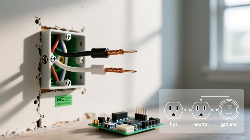
- Prep the Conductors: Strip exactly 3/4 inch of insulation from the black (hot), white (neutral), and bare (ground) wires. Do not leave excess bare copper exposed outside the terminal block.
- Connect the Ground: Loop the bare copper wire clockwise around the green grounding screw on the GFCI. Tighten securely.
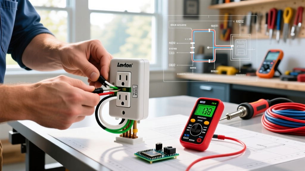
- Connect LINE Terminals: Because this is a single-location installation (no downstream outlets), you will only use the LINE terminals. Connect the black wire to the brass LINE screw and the white wire to the silver LINE screw. Ensure the wire loop is fully seated under the screw head with no insulation caught beneath it.
- Apply Correct Torque: This is where amateurs fail. The Leviton GFNT2-W requires 14 to 16 inch-pounds of torque on the terminal screws. Under-tightening causes micro-arcing and heat buildup; over-tightening strips the brass threads. Use a calibrated torque screwdriver to click precisely at 15 inch-pounds.
- Secure the Device: Fold the wires neatly into the back of the box using a 'Z' fold pattern to avoid pinching the conductors against the box walls. Secure the GFCI to the box using the provided 6-32 machine screws.
Phase 4: Weatherproofing and Final Testing
The final barrier against the elements is the while-in-use cover.
- Install the Foam Gasket: The TayMac MM410C comes with a thick foam gasket. Press it firmly against the face of the mounted exterior box.
- Mount the Cover: Align the cover's mounting holes with the box's threaded hubs. Use the provided stainless steel screws to secure the cover. Apply a small dab of clear silicone over the top two screw heads to prevent water wicking into the threads.
- Energize and Test: Remove the painter's tape and turn the 20A breaker back on. The GFCI's green LED indicator should illuminate. Press the 'TEST' button; the outlet should trip with an audible click, and the LED should turn off. Press 'RESET' to restore power.
Troubleshooting Matrix: GFCI Nuisance Tripping
If your newly installed outdoor receptacle trips immediately or intermittently, consult this diagnostic matrix before replacing the device.
| Symptom | Probable Cause | Expert Resolution |
|---|---|---|
| Trips immediately upon reset | Neutral-to-Ground fault downstream or reversed LINE/LOAD. | Verify black/white are on LINE brass/silver. Check for pinched neutral wire touching the grounded metal box or ground wire. |
| Trips only during heavy rain | Compromised while-in-use cover seal or missing foam gasket. | Inspect the TayMac cover hinge for debris preventing closure. Re-caulk the top edge of the cover plate to the siding. |
| Trips randomly when indoor appliances run | Shared neutral on a multi-wire branch circuit (MWBC). | Outdoor GFCIs cannot share a neutral with another circuit. You must run a dedicated 2-pole GFCI breaker or isolate the neutral. |
| Will not reset (no LED light) | Tripped upstream GFCI or open hot/neutral at the interior splice. | Check interior junction box for loose wire nuts. Verify no upstream GFCI in a garage or bathroom has tripped, cutting power to this line. |
By adhering to these precise material specifications, box-fill calculations, and torque requirements, your exterior receptacle will provide safe, code-compliant power for decades, withstanding the harshest environmental conditions without nuisance tripping.