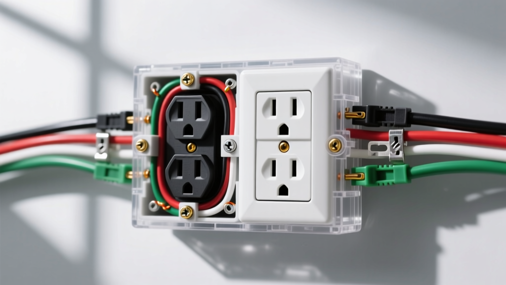

Understanding 240V Split-Phase Power
Before interpreting any 240v electrical outlet wiring diagram, you must understand the nature of North American split-phase power. Unlike standard 120V circuits that draw from a single hot leg and a neutral, a 240V circuit utilizes two 120V hot legs that are 180 degrees out of phase with each other. This yields 240V across the two hots, eliminating the need for a neutral wire in purely 240V loads (like baseboard heaters), but requiring one for appliances that mix 240V and 120V components (like electric dryers and ranges).
Working with 240V circuits carries a significantly higher risk of fatal arc flash and electrocution compared to 120V circuits. Always verify the absence of voltage using a CAT III or CAT IV rated multimeter before touching any conductor.
NEMA Receptacle Configuration Matrix
The National Electrical Manufacturers Association (NEMA) standardizes plug and receptacle configurations. Selecting the correct 240v electrical outlet depends entirely on the amperage draw and whether the appliance requires a neutral return path. Below is the definitive reference matrix for the most common residential and light-commercial 240V configurations.
| NEMA Type | Amperage | Voltage | Poles / Wires | Primary Application | Min. Copper Wire Gauge |
|---|---|---|---|---|---|
| 6-20R | 20A | 250V | 2P / 3W | Window AC units, heavy power tools | 12 AWG |
| 10-30R | 30A | 125/250V | 3P / 4W (Legacy 3-Prong) | Legacy electric dryers (pre-1996) | 10 AWG |
| 14-30R | 30A | 125/250V | 3P / 4W | Modern electric dryers | 10 AWG |
| 14-50R | 50A | 125/250V | 3P / 4W | Electric ranges, RV hookups, EV chargers | 6 AWG |
| 6-50R | 50A | 250V | 2P / 3W | Welders, plasma cutters (no neutral) | 6 AWG |
Wiring Diagram Logic: 4-Prong vs. 3-Prong Outlets
When wiring a 240v electrical outlet, the physical pin layout dictates the termination sequence. NEMA pins are universally designated as X (Hot 1), Y (Hot 2), W (Neutral), and G (Ground).
The Modern Standard: 4-Prong Wiring (NEMA 14-30 & 14-50)
Since the 1996 National Electrical Code (NEC) revision, 4-prong receptacles have been mandatory for new installations of ranges and dryers. This separates the equipment grounding conductor from the neutral, preventing return current from energizing the appliance chassis in the event of a neutral fault.
- X Terminal (Brass): Connect the Black (Hot 1) wire.
- Y Terminal (Brass): Connect the Red (Hot 2) wire.
- W Terminal (Silver): Connect the White (Neutral) wire.
- G Terminal (Green): Connect the Bare or Green (Ground) wire.
Expert Tip: For NEMA 14-50R installations supporting Level 2 EV chargers, ensure you are using a 4-wire cable (e.g., 6/3 NM-B with ground). Many modern EVSE units monitor the ground pin impedance and will fault if the ground is not properly bonded to the panel's ground bus.
The Legacy Configuration: 3-Prong Wiring (NEMA 10-30)
You will only encounter 3-prong 240v electrical outlet setups in older homes where the circuit has not been updated. In a NEMA 10-30 setup, there is no dedicated ground wire; the neutral serves as the return path and is bonded to the appliance chassis.
- X Terminal: Connect Black (Hot 1).
- Y Terminal: Connect White (acting as Hot 2, must be re-identified with black tape).
- W Terminal: Connect the Bare wire (which acts as both Neutral and Ground in legacy 10/2 NM cable).
Warning: The NEC strictly prohibits installing new 3-prong 240V receptacles. If you are running a new circuit, you must install a 4-prong receptacle and update the appliance cord accordingly.
Step-by-Step Installation & Termination Protocol
Proper termination is where most DIYers fail, leading to high-resistance connections and melted receptacles. Follow this exact sequence for a safe installation.
- Panel Preparation: Turn off the main breaker. Install a 2-pole breaker of the correct amperage. For a 30A circuit, use a 30A 2-pole breaker (e.g., Square D HOM230). For a 50A circuit, use a 50A 2-pole breaker.
- Cable Routing: Route the appropriate NM-B or THHN in conduit. Strip the outer jacket, leaving at least 8 inches of individual conductors inside the receptacle box.
- Wire Stripping: Strip exactly 3/4 inch of insulation from the individual conductors. Do not nick the copper, as this creates a stress fracture point that can snap under thermal expansion.
- Termination & Torque: Insert the wires into the receptacle terminals. Per NEC 110.14(D), you must use a calibrated torque screwdriver to tighten the terminal screws. For 10 AWG and 8 AWG copper, the typical torque specification is 14 to 16 in-lbs. For 6 AWG, it is typically 35 to 45 in-lbs. Check the manufacturer's stamp on the receptacle yoke for exact values.
- Box Mounting: Secure the receptacle to the box using the provided 6-32 screws. Ensure the yoke is flush against the drywall or tile to prevent the faceplate from cracking when a heavy plug is inserted.
Continuous Load Calculations for EV Chargers
A critical edge case in 240v electrical outlet wiring is the installation of NEMA 14-50 receptacles for Electric Vehicle Supply Equipment (EVSE). EV charging is classified as a continuous load (operating for 3 hours or more).
According to NEC Article 210.20(A), continuous loads require the branch circuit to be rated at 125% of the actual load. Therefore, if you purchase a 40-Amp continuous EV charger, you cannot use a 40-Amp breaker. You must multiply 40A by 1.25, resulting in a 50-Amp breaker requirement. This necessitates a NEMA 14-50 receptacle and 6 AWG copper wire. Attempting to run a 40A continuous load on a 40A breaker will cause nuisance tripping as the breaker's thermal element heats up over time.
Troubleshooting Common 240V Receptacle Failures
If your appliance is not functioning after wiring the 240v electrical outlet, use a multimeter to diagnose the following specific failure modes:
1. Appliance Runs but Heater Element is Dead
Diagnosis: You are reading 120V across X-to-G and Y-to-G, but only 0V across X-to-Y.
Cause: One of the hot legs is dead. This usually indicates a tripped breaker, a loose connection at the panel bus bar, or a broken conductor inside the NM-B cable. Check the 2-pole breaker to ensure both poles are fully seated in the 'ON' position.
2. Dryer Tumbles but Produces No Heat (4-Prong Setup)
Diagnosis: The motor runs (120V component), but the heating element (240V component) does not engage.
Cause: Open neutral or missing L2 leg. Verify 240V across the X and Y terminals at the receptacle. If you have 240V at the receptacle, the failure is likely the appliance's internal pigtail cord connection, not the wall outlet.
3. GFCI/AFCI Breaker Nuisance Tripping
Diagnosis: The 2-pole breaker trips immediately upon plugging in the appliance.
Cause: If using a GFCI breaker, ensure the neutral pigtail from the breaker is connected to the panel's neutral bar, and that the circuit's neutral wire is connected to the breaker's neutral terminal, not the panel's neutral bar. Bypassing the breaker's neutral coil will cause an immediate ground-fault trip. For deeper grounding and wiring method compliance, refer to OSHA standard 1910.305 regarding proper grounding paths.
Final Safety Verification
Before applying power to the main panel, perform a continuity test. Set your multimeter to the continuity (beep) setting. Place one probe on the receptacle's Ground pin (G) and the other on the metal outlet box. It should beep, confirming a solid ground path. Next, place one probe on the Neutral pin (W) and the other on the Ground pin (G). It should not beep. If it does, you have a bootleg ground or a crossed neutral/ground wire that must be corrected before energizing the circuit.


