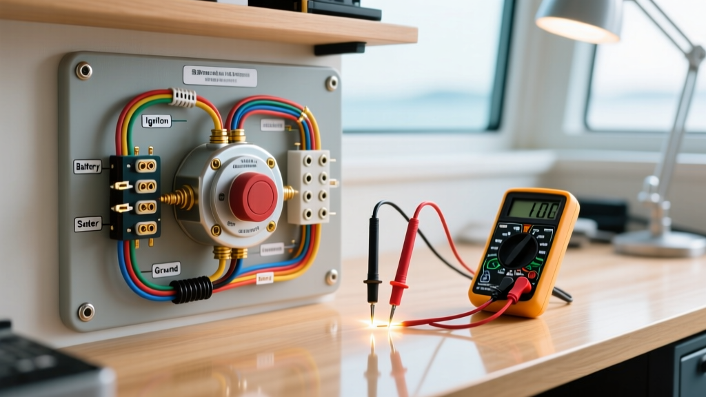

Decoding the Ignition Switch Wiring Diagram for Boat Electrical Systems
Marine environments are notoriously hostile to electrical components. Salt spray, high humidity, UV exposure, and constant engine vibration accelerate corrosion and mechanical wear. When your outboard or sterndrive refuses to crank, or your engine won't shut off when you turn the key, the ignition switch is a primary suspect. However, blindly replacing parts based on guesswork wastes time and money. Professional marine electricians rely on a systematic approach, using an accurate ignition switch wiring diagram for boat applications to isolate faults. This inspection and testing guide will walk you through terminal identification, multimeter diagnostics, and real-world failure modes specific to marine 12V DC systems.
Anatomy of a Universal Marine Ignition Switch
While OEM switches from Yamaha, Mercury, or Volvo Penta have proprietary pinouts, the vast majority of aftermarket replacements (such as the Cole Hersee M-750 series or Sierra MP41040) utilize a standardized 6-post universal configuration. Understanding these terminal designations is the first step in reading your diagram.
- B (Battery): The primary 12V+ input from the main battery bank, usually protected by a 20A to 30A inline fuse or circuit breaker.
- I (Ignition): Outputs 12V+ in the "Run" and "Start" positions. Powers the engine control module (ECM), gauges, and fuel pump relay.
- S (Starter): Outputs 12V+ only in the "Start" (crank) position. Engages the starter solenoid.
- M (Magneto): Specific to outboards. Grounds the ignition coil to kill the spark when the key is in the "Off" position.
- C (Choke): Outputs 12V+ when the key is pushed in (or turned to a dedicated choke position) to activate the choke solenoid on carbureted engines.
- A (Accessory): Outputs 12V+ in "Run" to power secondary dash loads like bilge blowers or radios.
The Continuity Matrix: Mapping the Diagram
Before testing, you must know what the switch should do. The table below represents the internal continuity states for a standard universal 6-post marine ignition switch.
| Key Position | B to I (Ignition) | B to S (Starter) | B to A (Accessory) | M to Ground (Kill) |
|---|---|---|---|---|
| OFF | Open | Open | Open | Closed (Continuity) |
| RUN | Closed | Open | Closed | Open |
| START (Crank) | Closed | Closed | Open (Usually) | Open |
Phase 1: Voltage Drop Testing the 'B' Terminal
A common mistake is testing for continuity with the battery disconnected. A switch might pass a low-current continuity test but fail catastrophically under load due to internal carbon tracking. We begin with a live voltage drop test using a True-RMS digital multimeter (DMM) like the Fluke 87V or Klein Tools MM400.
- Set your DMM to DC Volts.
- Place the red probe on the main battery positive post (not the cable clamp, the actual lead post).
- Place the black probe on the 'B' terminal on the back of the ignition switch.
- Turn the key to the RUN position to activate dash loads.
Diagnostic Threshold: According to American Boat and Yacht Council (ABYC) E-11 Standards, the maximum acceptable voltage drop for a 12V DC circuit is 3% (0.36V) for navigation lights and 10% (1.2V) for non-navigation loads. However, for the primary ignition feed, you want to see a drop of less than 0.10V (100mV). If your meter reads 0.5V or higher, the fault is not the switch itself, but rather a corroded main harness connection, a failing main breaker, or undersized battery cables.
Phase 2: The 'S' Terminal Dummy Load Test
The starter solenoid on a typical outboard draws between 5 and 15 Amps during the initial engagement spike. If the internal copper contacts inside the 'S' terminal of your ignition switch are pitted or corroded, they will easily pass the 3-milliamp test current of a standard multimeter's continuity beep. But when asked to pass 12 Amps, the resistance will cause a massive voltage drop, resulting in the infamous "single click, no crank" symptom.
Pro-Tip: Build a 12V Dummy Load. To truly test the 'S' terminal, wire an 1156 automotive tail light bulb in parallel with your multimeter probes. Connect the positive lead to the 'S' terminal and the negative to a known good ground. Turn the key to START. If the bulb illuminates brightly and your meter reads above 10.5V, the switch contacts are healthy. If the bulb is dim or the voltage drops below 9V, the internal switch contacts are burned and the unit must be replaced.
Phase 3: Magneto Kill Circuit Diagnostics (The 'M' Terminal)
One of the most dangerous marine electrical failures is an engine that refuses to shut off when the key is turned to OFF. This is governed by the 'M' (Magneto) terminal.
How the Kill Circuit Works
Unlike automotive applications that cut power to stop the engine, outboard ignition systems are "make-to-ground." The ignition coils fire continuously unless their primary circuit is grounded. In the OFF position, the ignition switch internally connects the 'M' terminal to the switch's metal mounting bracket (which grounds to the dash, and subsequently to the engine block via the negative battery cable).
Testing the 'M' Terminal
- Set your DMM to Continuity (Ohms).
- Disconnect the main harness plug from the back of the switch to isolate it.
- Place one probe on the 'M' terminal pin and the other on the metal threaded barrel of the switch.
- Turn the key to OFF. You should read near 0.0 Ohms (a dead short).
- Turn the key to RUN. The meter should read OL (Open Loop / Infinite resistance).
Edge Case Failure: If the switch tests perfectly on the bench, but the engine still runs with the key off, the fault lies in the "M" wire running through the main rigging cable back to the engine. Vibration at the transom often breaks this specific wire inside its insulation. Refer to your specific ignition switch wiring diagram for boat rigging to trace the M-wire (usually black with a yellow sleeve) back to the engine harness plug.
Environmental Failure Modes & Prevention
When inspecting the physical switch, look beyond the electrical contacts. The NFPA 302 Fire Protection Standard for Pleasure and Commercial Motor Craft emphasizes the necessity of protecting electrical connections from moisture and physical damage.
- Neoprene Boot Degradation: High-quality switches feature a rubber neoprene boot behind the dashboard fascia to prevent water from running down the dash and into the switch barrel. Over 3 to 5 years, UV and ozone exposure cause these boots to dry-rot and crack. If you see cracking during inspection, replace the boot immediately, even if the switch still functions.
- Galvanic Corrosion at Terminals: If you see green/white crust on the brass spade terminals, the switch has been exposed to salt air. Do not simply spray it with WD-40. The corrosion wicks inside the switch housing via capillary action. The switch must be replaced, and the new terminals must be coated with a marine-grade dielectric grease (such as Boeshield T-9 or MarinePro).
- Overtightening the Mounting Nut: The internal wafer contacts are made of phenolic resin and thin copper. Using a wrench to overtighten the plastic or metal locking nut on the dash can warp the internal housing, causing the wafers to bind. This results in a key that is incredibly stiff to turn and eventually strips the internal plastic cam. Hand-tighten the nut, then use a strap wrench for the final quarter-turn.
Wire Sizing and Replacement Specifications
When replacing a faulty switch based on your diagram, ensure the wiring meets marine ABYC standards. The 'B' (Battery) feed wire must be sized to handle the cumulative load of all downstream accessories plus the starter solenoid. For a standard single-engine setup, use a minimum of 10 AWG marine-grade tinned copper wire for the 'B' feed. The 'I', 'S', and 'A' circuits can typically utilize 12 AWG, while the 'C' (Choke) and 'M' (Magneto) circuits can use 14 AWG. Always use adhesive-lined heat shrink terminals (ring terminals for the switch posts) to prevent moisture intrusion and ensure a gas-tight crimp.