
Decoding the Wiring Diagram for a 7-Way Plug
When towing heavy-duty trailers, fifth wheels, or RVs, the 7-way RV blade connector (governed by the SAE J286 standard) is the critical lifeline between your tow vehicle and trailer. Understanding the wiring diagram for a 7-way plug is not just about matching wire colors; it is about verifying wire gauge, circuit isolation, and load capacity. In 2026, with modern tow vehicles utilizing complex multiplex CAN-bus electrical systems, assuming a standard 12V DC analog output at the bumper can lead to blown vehicle control modules if the trailer side harbors a hidden short.
This inspection and testing guide moves beyond basic plug-and-play assumptions. We will cover exact pinout specifications, professional multimeter testing procedures, and the hidden failure modes that cause erratic trailer brake behavior and lighting backfeed.
The Standard 7-Way Pinout Matrix
Before testing, you must understand the baseline architecture. The following table outlines the standard SAE J286 pinout, standard wire colors, and the minimum American Wire Gauge (AWG) required to prevent voltage drop and overheating.
| Pin Position | Function | Standard Wire Color | Minimum AWG |
|---|---|---|---|
| 1 (Top Center) | Ground (White) | White | 10 AWG (8 AWG preferred) |
| 2 (Top Right) | Electric Brakes | Blue | 10 AWG |
| 3 (Bottom Right) | Tail / Running Lights | Brown | 12 AWG |
| 4 (Center Left) | Left Turn / Stop | Yellow | 12 AWG |
| 5 (Center Right) | 12V Auxiliary / Battery Charge | Black or Red | 10 AWG |
| 6 (Bottom Left) | Right Turn / Stop | Green | 12 AWG |
| 7 (Bottom Center) | Reverse Lights / Aux | Purple | 12 AWG |
For deeper reference on OEM variations and adapter harnesses, etrailer's comprehensive wiring FAQ remains an industry-standard resource for mapping non-standard factory tow packages to the universal 7-way layout.
Essential Tools for 7-Way Connector Inspection
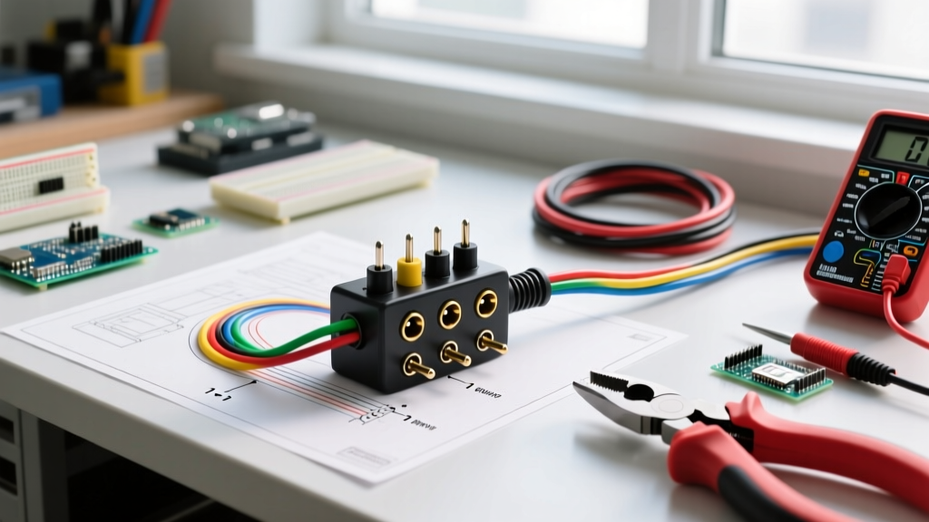
To properly diagnose a 7-way plug, visual inspection is insufficient. You need to measure voltage under load and test continuity. Assemble the following toolkit:
- Digital Multimeter (DMM): A True-RMS meter like the Fluke 117 (approx. $195) is ideal for reading fluctuating DC voltages from modern PWM (Pulse Width Modulation) brake controllers.
- 7-Way Circuit Tester: The Curt 57101 or Tekonsha 7-Way Tester (approx. $16-$22) provides immediate visual LED confirmation of pin activation without needing a second person in the cab.
- Dielectric Grease: Permatex 22058 (approx. $6) is mandatory for resealing connections to prevent galvanic corrosion between copper wire and brass pins.
- Wire Piercing Probes: For testing voltage drop along the trailer tongue without stripping back weather-sealed insulation.
Step-by-Step Continuity and Voltage Testing
Follow this systematic approach to isolate faults between the tow vehicle and the trailer.
Phase 1: Tow Vehicle Output Verification
- Ground Reference: Set your multimeter to DC Volts. Place the black probe on a known clean chassis ground on the tow vehicle, and the red probe on Pin 1 of the vehicle-side 7-way receptacle. The reading should be 0.00V. Any voltage here indicates a compromised vehicle ground.
- 12V Aux & Running Lights: Turn on the vehicle's headlights. Probe Pin 3 (Brown). You should see 13.2V to 14.4V (engine running). Next, probe Pin 5 (Black/Red). If this pin reads 0V, your vehicle's factory tow package may require an under-hood relay activation (common in GM and Ford trucks from 2018-2026).
- Brake Controller Output: Have an assistant press the manual override lever on your in-cab brake controller. Probe Pin 2 (Blue). You should see a smooth ramp-up from 0V to 12V+, or a rapid PWM square wave averaging 12V depending on your controller model (e.g., Tekonsha Prodigy P3 vs. Curt Echo).
Phase 2: Trailer Side Continuity & Load Testing
Disconnect the trailer. Set your multimeter to Ohms (Continuity). Test from the trailer plug pins to the actual component grounds at the rear of the trailer. A reading of OL (Open Loop) means a broken wire. A reading below 1.0 Ohm confirms a healthy path. Always consult the Recreation Vehicle Industry Association (RVIA) standards for acceptable resistance thresholds in manufactured RVs.
Common Failure Modes & Edge Cases
Experienced technicians know that the wiring diagram for a 7-way plug only tells half the story. The real-world environment introduces severe edge cases.
The "Ground Backfeed" Phenomenon
If Pin 1 (White Ground) becomes corroded or loose at the trailer tongue, the return current for the running lights (Pin 3) will seek an alternative path back to the vehicle chassis. It often backfeeds through the brake controller circuit (Pin 2) or the 12V aux (Pin 5). Symptom: The trailer brakes lock up randomly when you turn on the headlights, or the interior RV lights flicker in time with your turn signals. Fix: Upgrade the ground wire to 8 AWG and bond it directly to the trailer frame using a star washer and bare-metal contact point, bypassing the plug entirely for high-draw accessories.
Multiplex Wiring Sensitivities
Modern vehicles use multiplex wiring networks that monitor current draw to detect short circuits. If your trailer's 12V auxiliary circuit (Pin 5) is used to charge a massive RV battery bank, the initial inrush current can exceed the vehicle's CAN-bus threshold, causing the BCM (Body Control Module) to permanently shut off the tow circuit until a dealer resets it via OBD2 scanner. Fix: Install an isolation relay or a dedicated DC-DC charger (like the Redarc BCDC1225D) at the trailer tongue to buffer the draw.
Expert Callout: Moisture Ingress Shorts
A frequent cause of "ghost" trailer brakes is moisture ingress inside the 7-way plug housing itself, creating a high-resistance short between Pin 2 (Brakes) and Pin 5 (12V Aux). When it rains, the 12V aux power bleeds into the brake circuit, applying 2-4 volts to the trailer magnets. Always pack the rear of the plug housing with dielectric grease and wrap the junction in self-amalgamating silicone tape, not standard vinyl electrical tape which degrades under UV exposure.
Troubleshooting Matrix: Symptom to Solution
Use this diagnostic matrix to quickly pinpoint issues based on multimeter readings and physical symptoms.
| Observed Symptom | Probable Cause | Multimeter Reading | Corrective Action |
|---|---|---|---|
| Trailer brakes lock up when headlights are on. | Ground backfeed via Pin 2. | 2V - 5V DC on Pin 2 when headlights are active. | Clean Pin 1; add dedicated 8 AWG chassis ground. |
| Dim or flickering running lights on trailer. | Voltage drop on Pin 3 (Brown). | Less than 11.5V DC at the rear trailer marker light. | Check for corrosion at plug; upgrade to 10 AWG if over 30ft. |
| Brake controller shows "S.H." or Short Circuit. | Pin 2 (Blue) shorted to ground. | 0.0 Ohms between Pin 2 and Pin 1 on trailer side. | Inspect trailer tongue for pinched blue wire near the A-frame. |
| RV battery fails to charge while towing. | Vehicle Pin 5 relay missing or blown. | 0V DC on vehicle Pin 5 with engine running. | Check under-hood fuse box for "Trailer Aux" relay/fuse. |
Final Inspection & Maintenance Protocols
Proper maintenance of your 7-way connector ensures safety and prevents costly damage to both your tow vehicle's electrical system and your trailer's components. After completing your tests and verifying that all voltage drops remain below 0.2V on 10 AWG circuits and 0.5V on 12 AWG circuits, apply a liberal coat of dielectric grease to the male pins before insertion.
Furthermore, always support the heavy trailer-side cable with a bungee or strain-relief bracket to prevent the weight of the wire from pulling the pins out of alignment inside the socket. For commercial and heavy-duty applications, refer to Curt Manufacturing for heavy-duty cast-metal 7-way housings that resist the physical deformation common in cheaper plastic OEM receptacles. By combining a strict adherence to the wiring diagram with rigorous electrical testing, you guarantee a safe, compliant, and reliable towing experience.