
Decoding the Wiring Diagram for 3 Way Dimmer Switch Circuits
Upgrading a standard 3-way switch circuit to include dimming capabilities is one of the most common, yet frequently misunderstood, residential electrical projects. Unlike a single-pole switch where power flows linearly from the source to the load, a 3-way circuit utilizes a complex web of traveler wires to allow control from two separate locations. When you introduce a dimmer into this equation, the physical wiring layout of your home dictates exactly which wiring diagram for 3 way dimmer switch setups you must follow.
In 2026, with the near-universal adoption of dimmable LED fixtures and stringent energy codes, understanding the nuances of line voltage, load paths, and neutral wire requirements is critical. This guide breaks down the exact wiring scenarios, specific product architectures (focusing on the industry-standard Lutron Maestro LED+), and the edge cases that cause DIY installations to fail.
The Golden Rule of Standard 3-Way Dimming
Before pulling any wires, you must understand the fundamental limitation of standard hardwired 3-way dimmers: you can only install a physical dimmer in ONE of the two switch boxes. The second location must remain a standard 3-way toggle switch (like the Leviton 5603). The dimmer acts as the "master" controller, regulating the voltage sent through the traveler wires to the secondary switch, which then routes it to the light fixture. If you want physical dimming sliders at both locations, you must abandon standard hardwired diagrams and pivot to a smart lighting ecosystem with wireless companions.
Core Wire Identification in 3-Way Circuits
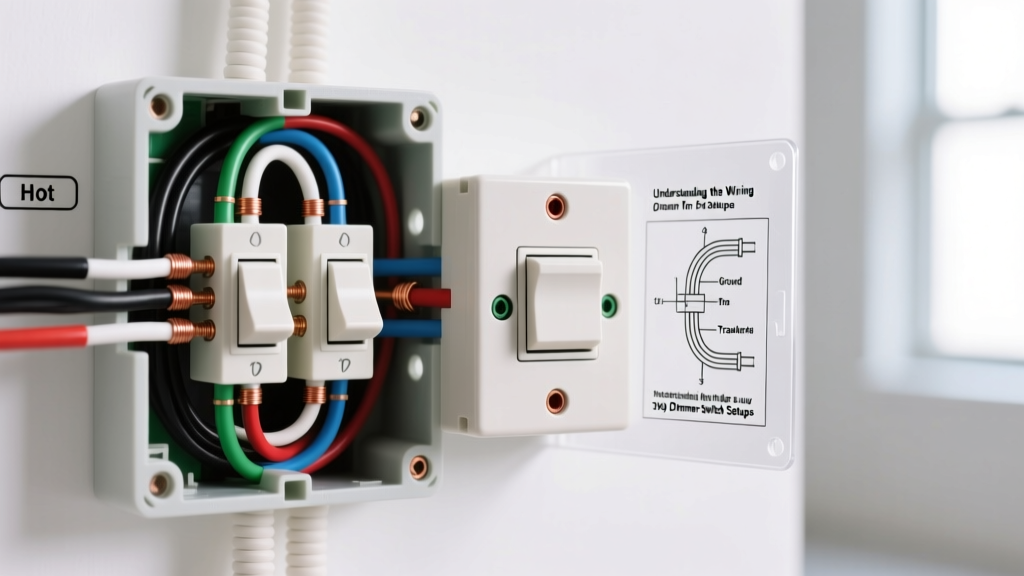
To successfully interpret any wiring diagram for 3 way dimmer switch configurations, you must correctly identify the five potential wire types in your junction boxes:
- Line (Hot): The unswitched 120V power coming from the breaker panel. Usually black, but always verify with a non-contact voltage tester.
- Load: The wire carrying power from the switch to the light fixture. Often black or red.
- Travelers: Two wires that run between the two 3-way switch boxes, carrying the switched current back and forth. Typically, these are red and black, or two wires of the same color in a 14/3 or 12/3 Romex cable.
- Neutral: The white wire completing the circuit back to the panel. Note: Standard analog dimmers do not use a neutral, but modern smart dimmers and some advanced LED dimmers absolutely require it.
- Ground: Bare copper or green insulated wire for safety fault clearing.
Scenario 1: Line and Load in the Same Switch Box
This is the most straightforward scenario and the most common in modern construction. Power from the breaker enters Box A, and the cable going up to the light fixture also originates in Box A. Box B simply acts as a remote toggle.
Wiring Execution:
- Box A (Dimmer Location): Connect the Line wire to the dimmer's black (hot) lead. Connect the Load wire to the dimmer's blue (load) lead. Connect the two Traveler wires to the dimmer's brass traveler terminals. Cap the neutral wires together in the back of the box (unless your specific dimmer requires a neutral connection, in which case connect it to the dimmer's white lead).
- Box B (Standard Toggle): Connect the two Traveler wires to the brass traveler screws on the standard 3-way toggle. Connect the Line wire (which is acting as the common feed from Box A in this specific topology) to the black common screw.
Scenario 2: Line and Load in Opposite Switch Boxes
In this scenario, power enters Box A, but the light fixture is wired directly from Box B. This means the traveler wires must carry the unswitched line voltage from Box A to Box B, where the secondary switch then sends it to the load.
Wiring Execution:
- Box A (Dimmer Location): Connect the incoming Line wire to the dimmer's black (hot) lead. Connect the two Traveler wires to the brass traveler terminals. The Load terminal on the dimmer remains empty in this specific configuration, as the load is handled at Box B.
- Box B (Standard Toggle): Connect the two Traveler wires to the brass traveler screws. Connect the Load wire (going to the fixture) to the black common screw.
Pro-Tip for Scenario 2: Many budget dimmers on the market will flicker or fail to initialize in Scenario 2 because they rely on sensing the load at the master switch to calibrate their internal TRIAC or MOSFET. Always use a high-quality dimmer like the Lutron Maestro LED+ (MACL-153M), which utilizes advanced digital sensing to handle remote-load topologies without ghosting.
Standard vs. Smart 3-Way Dimmer Comparison
When planning your upgrade, you must choose between a traditional hardwired dimmer and a smart ecosystem. The wiring diagrams differ vastly between the two.
| Feature | Lutron Maestro LED+ (MACL-153M) | Lutron Caseta (PD-5S-DV) |
|---|---|---|
| Average Cost (2026) | $35 - $42 USD | $60 USD (Switch only) |
| Secondary Switch | Standard 3-Way Toggle (~$4) | Pico Remote (~$18) or Companion Switch |
| Neutral Wire Required? | No (but recommended for large LED loads) | Yes (Strictly required) |
| Wiring Complexity | Moderate (Follows standard 3-way diagrams) | High (Requires rewiring travelers to act as line/load) |
| Dimming from Both Locations? | No (Only at the Maestro unit) | Yes (Via wireless Pico remotes at both boxes) |
Step-by-Step: Wiring the Lutron Maestro LED+ (MACL-153M)
The Lutron Maestro LED+ remains the benchmark for residential 3-way dimming due to its ability to handle mixed LED loads without requiring a neutral wire in most setups. Here is the precise installation sequence:
- Kill the Power: Turn off the breaker and verify zero voltage at both boxes using a CAT III or CAT IV multimeter. Non-contact testers can yield false positives due to phantom voltage on traveler wires.
- Identify the Common Wire: On the existing switch you are replacing, identify the wire connected to the black (common) screw. This is either your Line or your Load.
- Strip and Prep: Strip wire insulation to exactly 1/2 inch. If using stranded wire, tin the ends with solder or use ferrule crimps to prevent stray strands from causing a short in the dimmer's terminal block.
- Make the Connections: Use the provided captive wire leads on the Maestro. Connect Black-to-Black (Line/Load), Blue-to-Blue (Load/Line), and the two Brass leads to the remaining traveler wires. Use yellow wire nuts for 3-wire junctions and red for 2-wire junctions.
- Calibrate the Dimmer: Once power is restored, the Maestro will automatically run a 10-second calibration sequence to detect the minimum and maximum voltage thresholds of your specific LED drivers. Do not touch the switch during this process.
Troubleshooting Common 2026 LED Dimming Failures
Even with a perfect wiring diagram for 3 way dimmer switch execution, LED technology introduces unique failure modes that incandescent bulbs never exhibited.
1. LED Ghosting (Lights stay faintly lit when off)
The Cause: Standard 3-way dimmers without a neutral wire leak a tiny amount of current (micro-amps) through the circuit to power their internal locator LED or digital memory. Modern high-efficiency LED drivers interpret this micro-current as a signal to turn on.
The Fix: Install a Lutron LUT-MLC Minimum Load Capacitor (approx. $8). This small, inline capacitor solders or wires directly across the load and neutral at the light fixture (not at the switch), absorbing the leakage current and eliminating the ghosting effect entirely.
2. Severe Flickering at Low Dimming Levels
The Cause: The total wattage of your LED fixtures is below the dimmer's minimum load requirement. While the Maestro MACL-153M is rated for 150W of LED, it requires a minimum of 15W to maintain a stable phase-cut waveform. If you are dimming three 4W LED recessed cans (12W total), the circuit will starve and flicker.
The Fix: Swap one of the LED bulbs for a higher wattage equivalent, or add a LUT-MLC capacitor to artificially increase the reactive load on the circuit.
3. The Secondary Switch Stops Working
The Cause: A miswired traveler configuration. If the Line/Load is connected to a brass traveler terminal instead of the black/blue main terminals on the dimmer, the secondary toggle will only work when the dimmer is set to a specific threshold, or not at all.
The Fix: Re-verify the common wire identification. The wire that was on the black screw of the old 3-way toggle must go to the black or blue wire of the dimmer, never to the brass traveler leads.
Code Compliance and Safety Standards
When modifying switch loops, you must adhere to the latest National Electrical Code (NEC). Specifically, NEC Article 404.2(C) mandates that a neutral wire must be present at virtually all switch boxes in new construction and major renovations. This was implemented specifically to accommodate smart switches and advanced dimmers that require a constant 120V reference to power their internal Wi-Fi or Zigbee radios.
If you are working in a pre-1990s home with a "switch loop" (where only a black and white wire drop down from the ceiling to the switch, with no neutral), you are legally permitted to install a standard non-neutral dimmer like the Maestro. However, if you wish to install a smart dimmer, you must either pull a new 14/3 or 12/3 cable from the fixture to the switch box to introduce a true neutral, or utilize a smart switch system that bypasses the neutral requirement via specialized bypass modules installed at the canopy.
For comprehensive safety guidelines regarding residential wiring and switch replacements, always consult the Electrical Safety Foundation International (ESFI) resources on switches and outlets. Furthermore, referencing the official Lutron Wiring Diagrams database is highly recommended before finalizing any smart home 3-way topology, as firmware updates and hardware revisions can occasionally alter terminal assignments.
Final Thoughts
Mastering the wiring diagram for 3 way dimmer switch setups is less about memorizing color codes and more about understanding the flow of current from the panel, through the travelers, to the load. By correctly identifying your line/load topology, respecting the minimum wattage requirements of modern LED drivers, and choosing the right hardware for your specific junction box constraints, you can achieve flawless, flicker-free dimming from multiple locations.